
Click or hover over parts of our website to see more.
Click to see our robot win the final round of the competition! :)
Team 28, also known as :ANGRY: or the Angry Reacts, is the highest numbered - and highest quality - team in the ECE 3400 maze exploration robot competition.
The AngryBot is fully autonomous and capable of line following, wall-following, tone detection, and IR detection and avoidance of other robots. In addition, it communicates its current location and surroundings using an RF transceiver to an external GUI base station as we map it. Our robot explores its surroundings with the Depth First Search graph algorithm, and while not included in the competition robot, we integrated a camera and FPGA to detect visual treasures. Our robots were built with an Arduino Uno, a DE0-nano FPGA, custom 3D-printed components, and various sensors and servos.
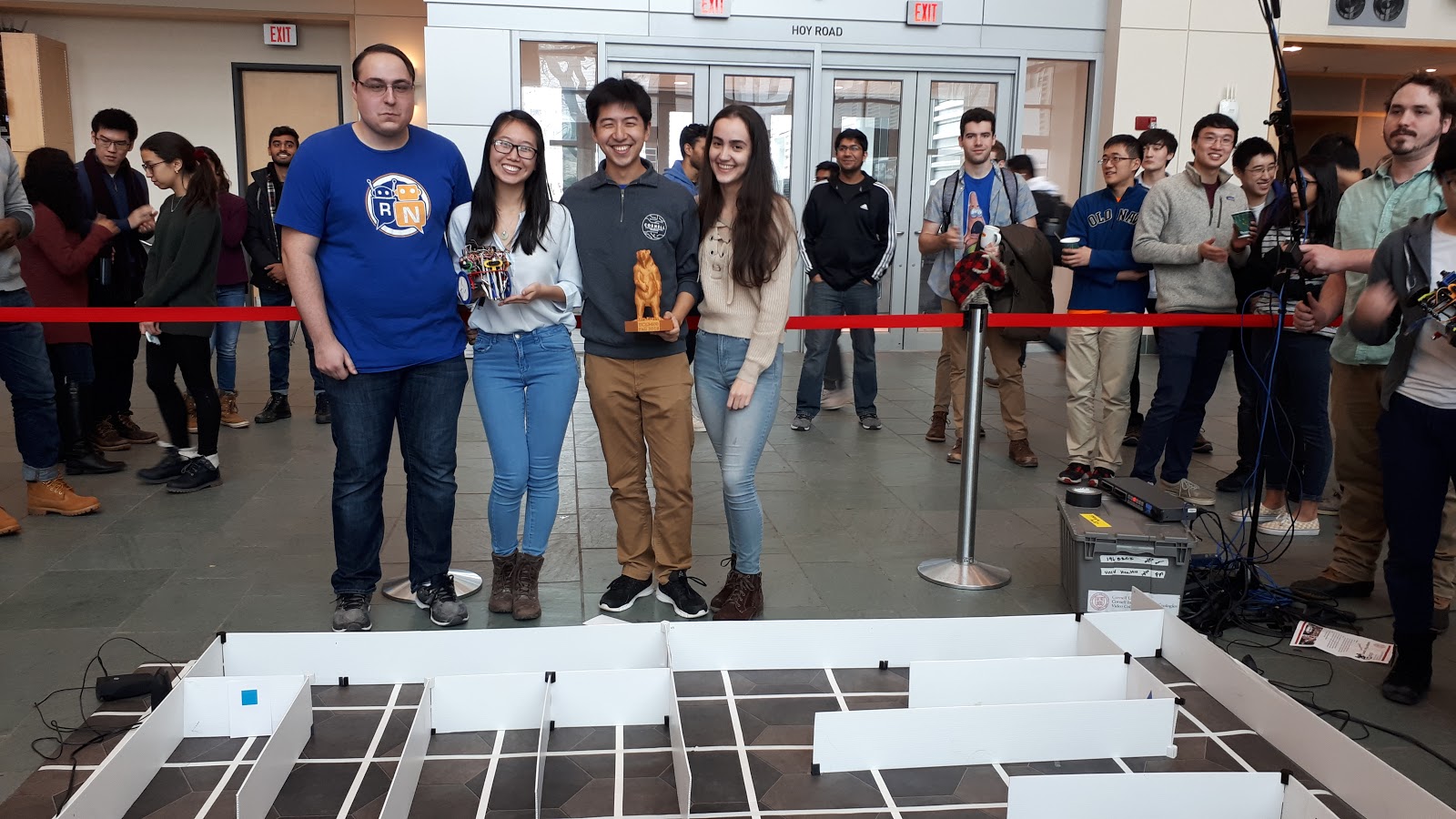
To the surprise of our team, our quick quip about being the highest quality team proved true; AngryBot mapped out the most squares in both the first and final rounds of the ECE 3400 competition on December 4th, leading us to a 1st place finish! Click on the photo to the photo of our robot to see a video of the final round.
For more about the competition or the robot, please take a look at the ECE 3400 course page or the final design write-up.


My focus during the final weeks was on IR detection, radio communication, and treasure detection (camera I2C communication and FPGA image processor).
To check out more of my work, take a look at my online resume here.
I really just wanted to show off that I found this cool CSS transition on StackExchange.
Microcontroller
In which we discover the Arduino Uno and start to get a moving robot.
Analog Circuitry and FFTs
In which we create detect tones and high frequency IR pulses.

System Integration and Radio
In which we talk to a GUI, and rediscover all of our sensors.

FPGA and Color Detection
In which we add a camera and learn the joys of visual processing.
Line Tracking
In which our robot learns to perform a figure eight.
Wall Detection
In which our robot learns to stop hitting itself.
Maze Exploration
In which our robot learns to search for what it wants.

Treasure Shape Detection
In which our robot learns to tell triangles from squares.
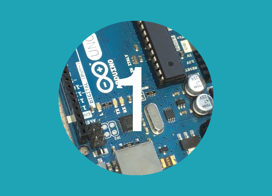
This lab introduces the Arduino Uno and Arduino IDE, and ends with the assembly of a basic robot performing autonomous driving. The lab takes approximately three hours, and requires the following materials:
LED_PIN, and modified the existing code to use this pin. We then changed the number assigned to the variable to test each digital pin. The following example tests digital pin 7.
const short LED_PIN = 7;

// the setup function runs once when you press reset or power the board
void setup() {
  // initialize digital pin LED_PIN as an output.
  pinMode(LED_PIN, OUTPUT);
}

// the loop function runs over and over again forever
void loop() {
  digitalWrite(LED_PIN, HIGH);       // turn the LED on (HIGH is the voltage level)
  delay(1000);                       // wait for a second
  digitalWrite(LED_PIN, LOW);        // turn the LED off by making the voltage LOW
  delay(1000);                       // wait for a second
}
To do this we started serial communication and then read the analog input using analogRead(INPUT_PIN). It should be noted that this does NOT return the actual voltage.
int INPUT_PIN = A0;

// the setup function runs once when you press reset or power the board
void setup() {
  Serial.begin(9600);
}

// the loop function runs over and over again forever
void loop() {
  delay(100);

  // Analog input read
  int input = analogRead(INPUT_PIN);
  Serial.println(input);
}
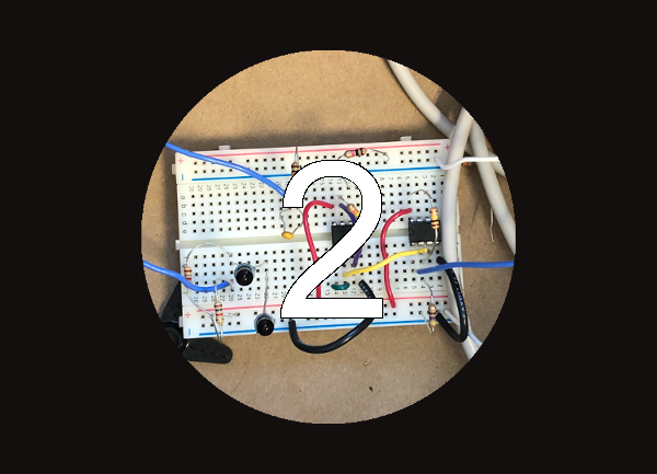
To set up the circuit we wired the output of the potentiometer to the Arudino’s A0(analog input) pin. We then supplied VCC to the wiper pin of the potentiometer and attached a 330 ohm resistor the the output of the potentiometer and GND to form a voltage divider.
analogWrite function, along with the pin connected to the LED.
We had to scale the potentiometer value because analogWrite only writes values from 0 to 255, whereas the 10-bit analog input results in a value from 0 to 1023. Different values for the potentiometer changed the brightness of the LED. The code is shown below.
const short LED_PIN = 11;
int INPUT_PIN = A0;

// the setup function runs once when you press reset or power the board
void setup() {
  // initialize digital pin LED_PIN as an output.
  pinMode(LED_PIN, OUTPUT);
  Serial.begin(9600);
}

// the loop function runs over and over again forever
void loop() {
  delay(100);

  // Analog input read
  int input = analogRead(INPUT_PIN);
  Serial.println(input);

  // PWM
  analogWrite(LED_PIN, input/4);
}
analogWrite, we imported the Servo.h library which takes care of setting the pin as an output and generating a proper waveform when we use its attach() and write() functions.
Again, the values had to be scaled, this time to the range of 0 to 180 that the servo library takes in for its write function. We also added some initial code which demonstrates the servo moving at full speed in both directions, and at a stop.
const short SERVO_PIN = 10;
int INPUT_PIN = A0;
Servo angrySpin;

// the setup function runs once when you press reset or power the board
void setup() {
  Serial.begin(9600);
  angrySpin.attach(SERVO_PIN);
  angrySpin.write(0);
  delay(1000);
  angrySpin.write(90);
  delay(1000);
  angrySpin.write(180);
  delay(1000);
}

// the loop function runs over and over again forever
void loop() {
  delay(100);

  // Analog input read
  int input = analogRead(INPUT_PIN);
  Serial.println(input);

  // PWM
  angrySpin.write(input/6);
}
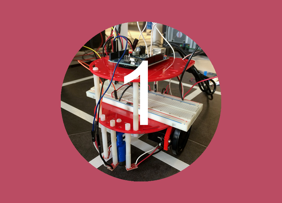
To begin, we attached the servos to the mounts, and then attached them to the base of the robot. We then attached the wheels, which took some time because not all wheels fit nicely into the servos. We had to get a bit creative when attaching the ball bearing because there was only one left and it was too short for our robot. We ended up attaching a piece to the base of the robot to elongate the part where the ball bearing attached. This temporarily solved the issue. Lastly, we mounted the arduino and the battery with velcro.
void setup() {
  // we set up two of our pins as outputs and attach our servos
    int PWM1 = 3;
    int PWM2 = 5;
    pinMode(PWM1, OUTPUT);
    pinMode(PWM2, OUTPUT);
    Motor1.attach(PWM1);
    Motor2.attach(PWM2);
}

void loop() {
  // we write a loop to control the speed and direction that the motors spin
    Motor1.write(180);
    Motor2.write(0);
    delay(1200);
    Motor1.write(90);
    Motor2.write(90);
    delay(600);
    turn();
}

void turn(){
  // this function turns the robot
    Motor1.write(180);
    Motor2.write(180);
    delay(350);
    Motor1.write(90);
    Motor2.write(90);
    delay(250);
    return;
}
View Lab 1 Code on GitHub
Close Lab 1
Create a microphone circuit that will detect a 660 Hz whistle blow signifying the beginning of our maze mapping.
We need at least a 660Hz x 2 = 1320Hz sampling rate based on the Nyquist sampling rate to avoid aliasing.
Using the sketch found here, these are the results of our speed test:
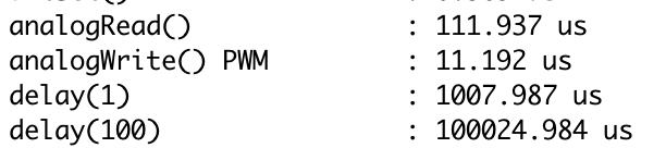
Based on this, analogRead() is sufficient (don’t need to use ADC) because its maximum rate is 111.987µs / sample = 1/111.987e-6 samples/s = 8930Hz, which is more than enough to detect the 660 Hz frequency.
We used the following materials:
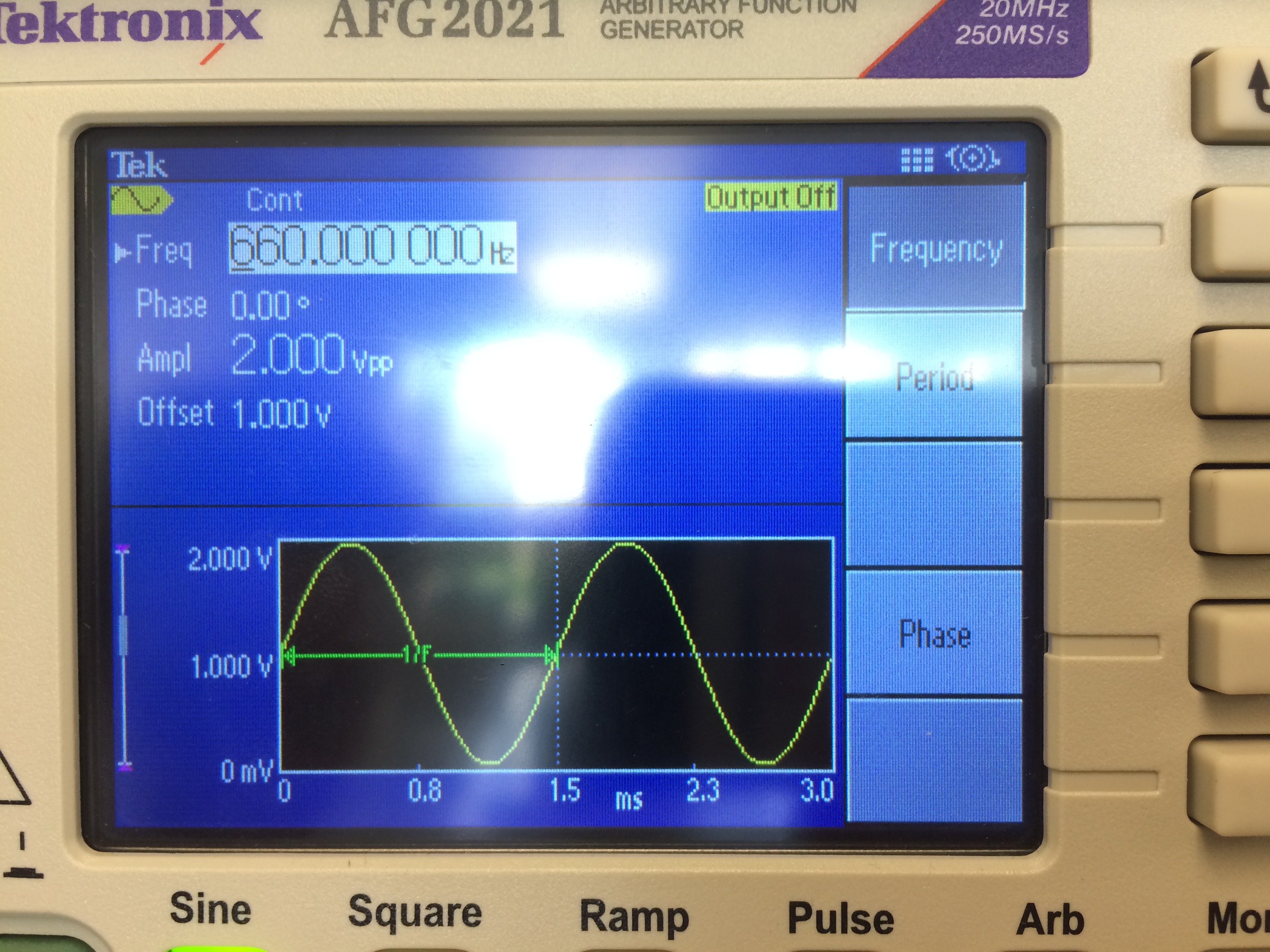
Unit Test 1: Set up a signal generator to deliver a signal that matches what you expect to see from your sensor. This signal must be between 0-5V to not damage the Arduino. Test that the frequency output from your signal generator matches what you see on the serial monitor.
The following is an image of our signal generator (set to 660Hz, 2Vpp, 1V offset)
We then coded a quick FFT analysis and output the results to the serial monitor:
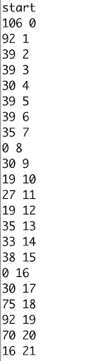
For each line in the image above, the first number is the output of the FFT, and the second number is the index of the bin for readability. As you can see, we have a peak at 0 and at 19. Our bin size should be around 8930Hz / 256samples = 34.883Hz/bin
So, our results make sense but are off by seemingly 1 bin.
Our FFT code:
#define LOG_OUT 1 // use the log output function
#define FFT_N 256 // set to 256 point fft

#include <FFT.h> // include the library

void setup() {
  Serial.begin(9600); // use the serial port
}

void loop() {
  cli();  // UDRE interrupt slows this way down on arduino1.0
  for (int i = 0 ; i < 512 ; i += 2) { // save 256 samples
    fft_input[i] = analogRead(A4); // put real data into even bins
    fft_input[i+1] = 0; // set odd bins to 0
  }
  fft_window(); // window the data for better frequency response
  fft_reorder(); // reorder the data before doing the fft
  fft_run(); // process the data in the fft
  fft_mag_log(); // take the output of the fft
  sei();
  Serial.println("start");
  String out = "";
  for (byte i = 0 ; i < FFT_N/2 ; i++) {
    Serial.println(out + fft_log_out[i] + " " + i); //send out data
  }
  while(1) {} // we inserted this so that it only prints one result
}
Unit Test 2: Use the app you downloaded during the pre-lab to generate a 660Hz tone. Measure the output from the microphone with the oscilloscope, and try to get an idea of what you need to do to the signal to be able to detect it securely from the Arduino.
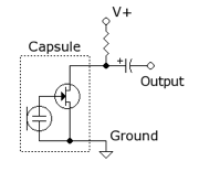
The following is the microphone circuit thus far, as taken from the lab handout:
After generating the tone, the microphone could not pick up the signal, but we knew the microphone was working because if we blew into the microphone the output would obviously change, as shown below:
Resting state of microphone
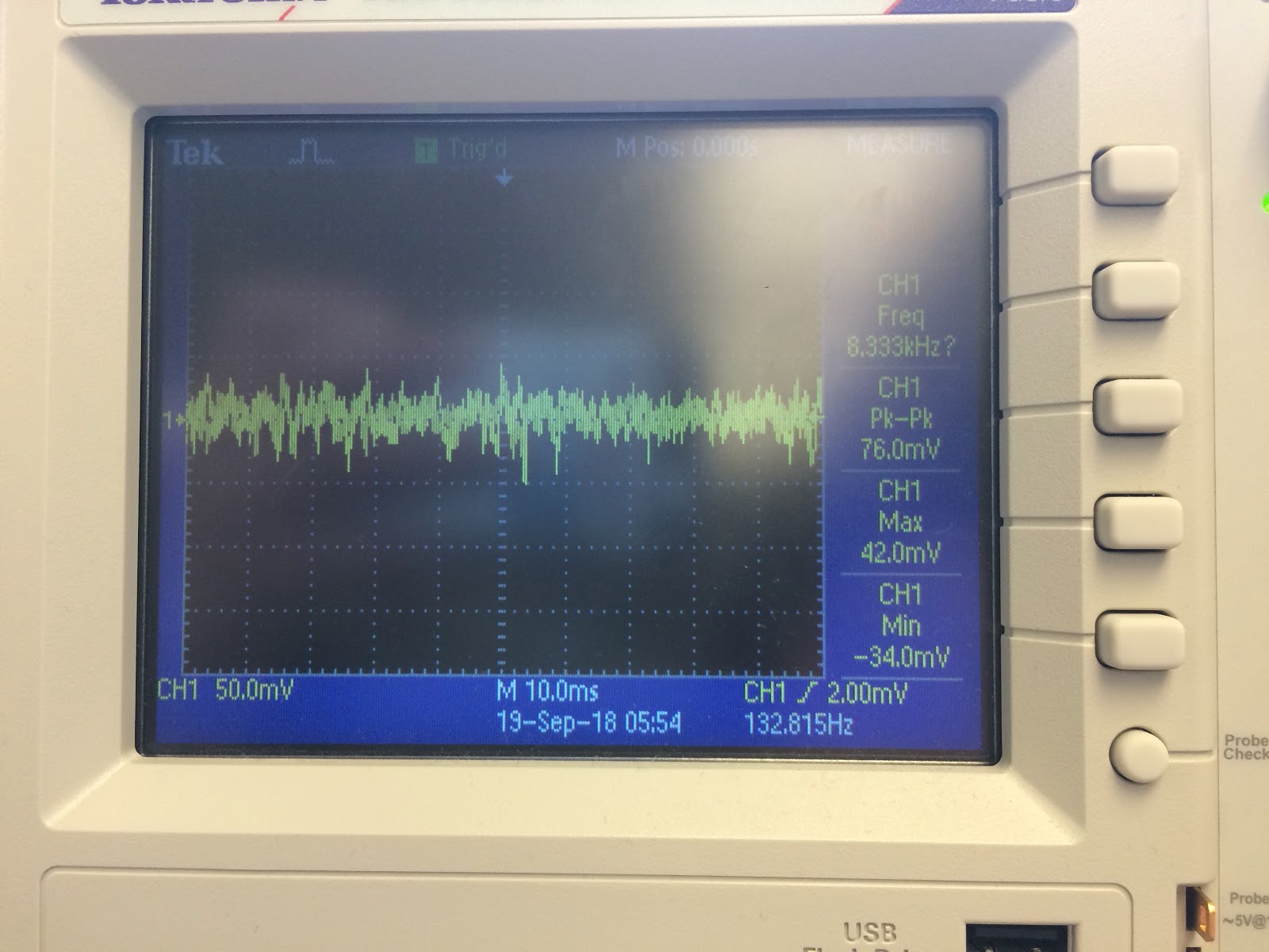
Microphone being blown on
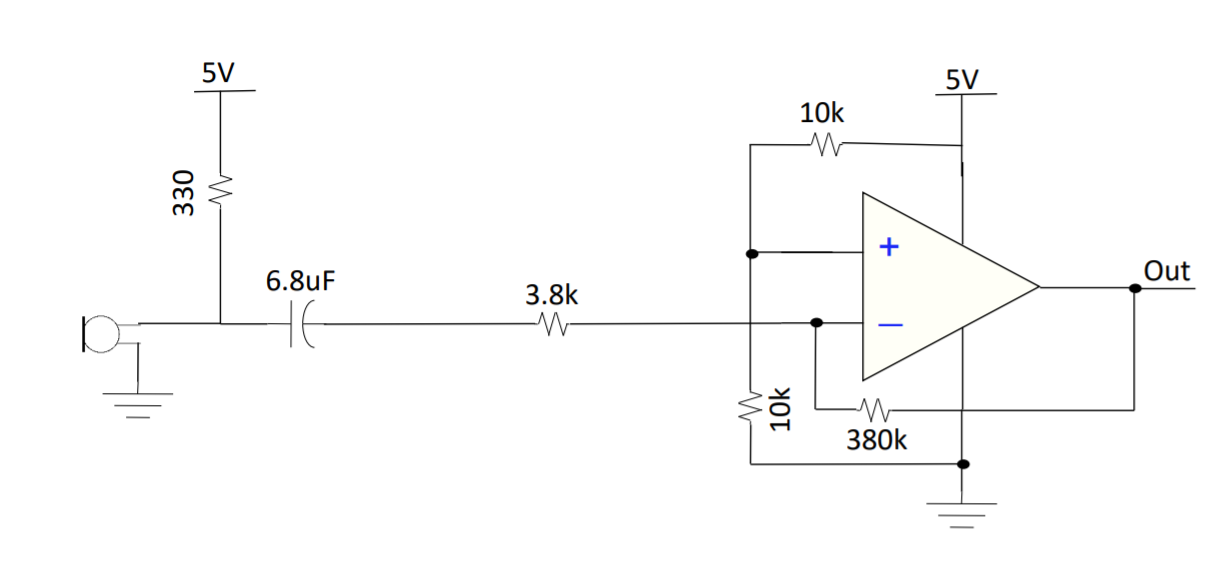
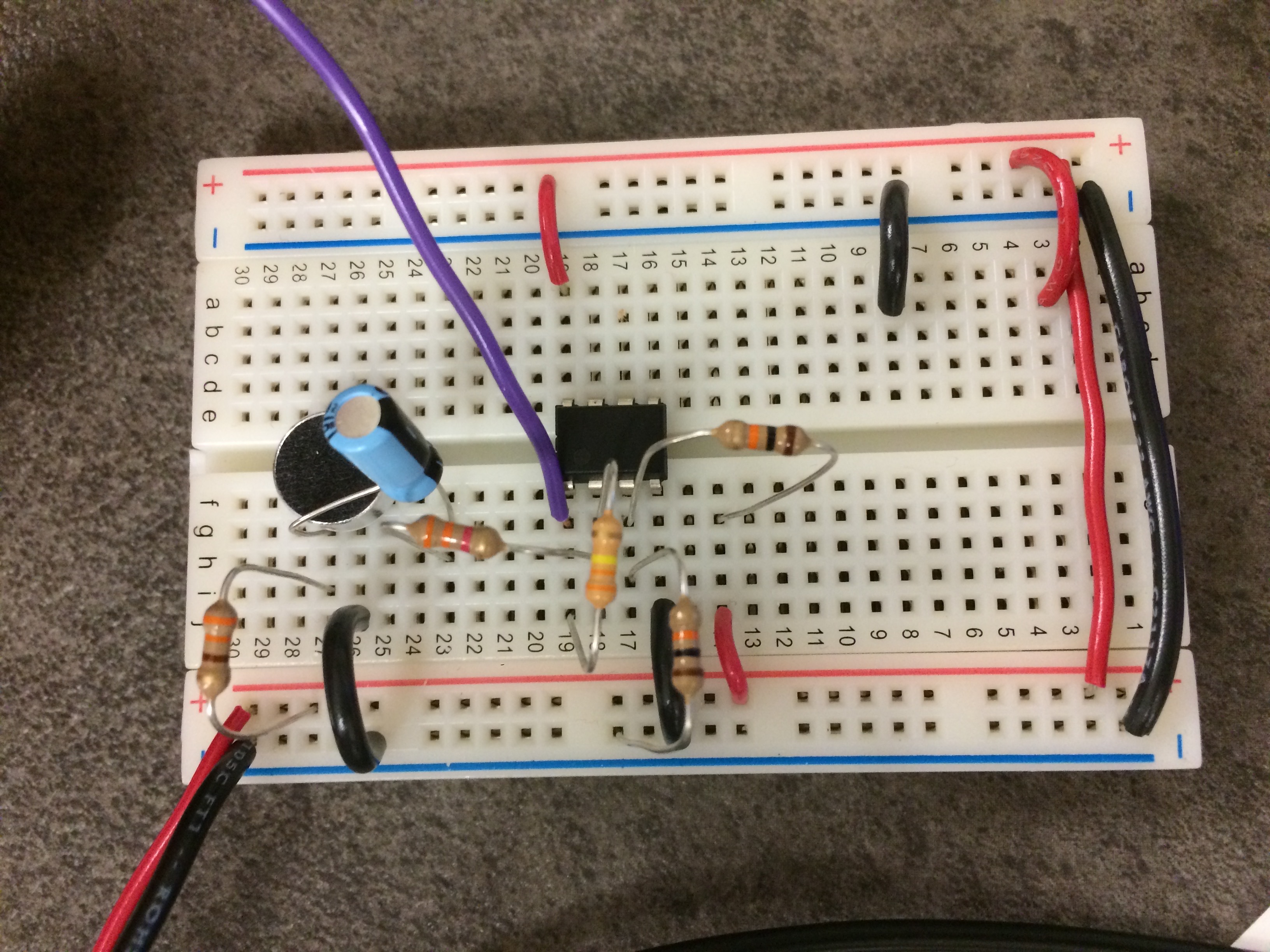
From this result, we decided to add an amplifier and a filter. After struggling to get our own design to work, we decided to use Team Alpha's design that incorporates an inverting amplifier, has a voltage divider to center the output voltage around 2.5V, and has a gain of 100:
Unit Test: Check your circuitry before hooking it up to the Arduino.
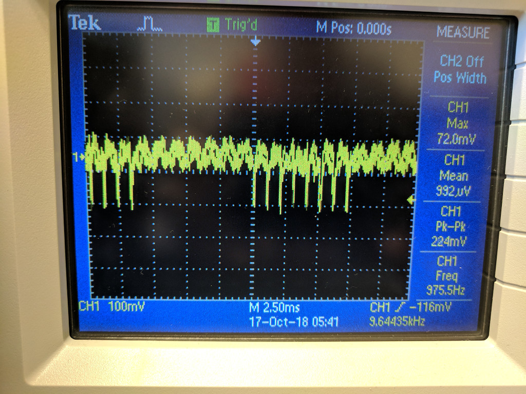
Below is the result of using the amplifier while playing a 660Hz tone, displayed on the oscilloscope:
Clearly, this signal can be sent into the Arduino as its minimum voltage is 2.12V and its peak-to-peak voltage is 840mV, which is well within the 0-5V range. The frequency is also correct.
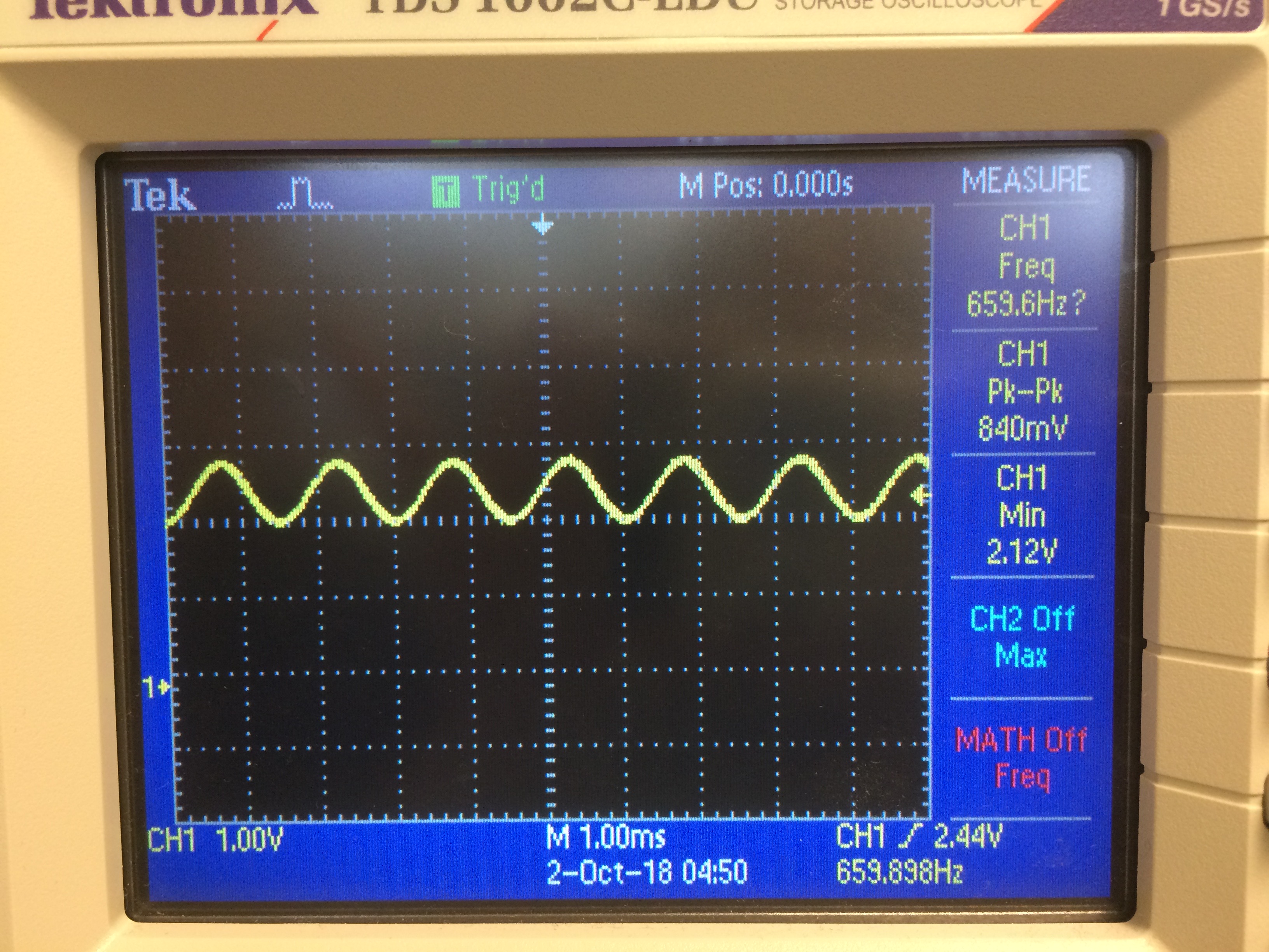
The following is a picture of the physical circuit, where the purple wire is the output signal:
After connecting the circuit to our robot and changing the code that controls how the robot starts to incorporate waiting for the 660Hz signal, this is a video of our successful result:
The following is our updated line following code to show that our robot waits for a signal before starting:
// In set-up, we wait while the signal has not been heard and the button has not been pressed:
while(!readSignal() && digitalRead(8) != HIGH);

// The following is our readSignal() method that calculates the FFT and returns true or false based on if the signal has been heard. We are reading the analog signal from A4:
boolean readSignal() {
  cli();  // UDRE interrupt slows this way down on arduino1.0
  for (int i = 0 ; i < 512 ; i += 2) { // save 256 samples
    fft_input[i] = analogRead(A4); // put real data into even bins
    fft_input[i+1] = 0; // set odd bins to 0
  }
  fft_window(); // window the data for better frequency response
  fft_reorder(); // reorder the data before doing the fft
  fft_run(); // process the data in the fft
  fft_mag_log(); // take the output of the fft
  sei();
  if (fft_log_out[19] >= 50){ // check that bin 19 contains a significant value
    return true;
  }
  return false;
}
Create a circuit which is able to detect a 6.08kHz IR signal signifying other robots which have to be avoided in the maze while discarding 18kHz decoy IR signals.
Unlike the microphone circuit, using AnalogRead will not be fast enough for IR purposes. We want to be able to detect 6kHz signals, which would require a sampling frequency of approximately 12kHz. However, the maximum with AnalogRead is approximately 8930Hz, as discussed above. Instead, we will have to read directly from the ADC pin result register to increase our sampling frequency. Since we will have to sample at such a high frequency, it will be difficult to do other processing simultaneously - we will have to carefully determine when to measure as to not miss other robots while were are making decisions about where to drive.
Thankfully, we don't have to worry as much about other sources of IR, which are unlikely to occur at the same frequency. For example, one common source of IR is fluorescent lights, but they emit approximately 30-60kHz signals. Testing in lab confirms that even in the presence of artificial lights and sunlike, the main source of noise for IR is 60Hz coming from the walls.
In order to build the amplification circuit, we needed the following materials in addition to our usual Arduino Uno setup:
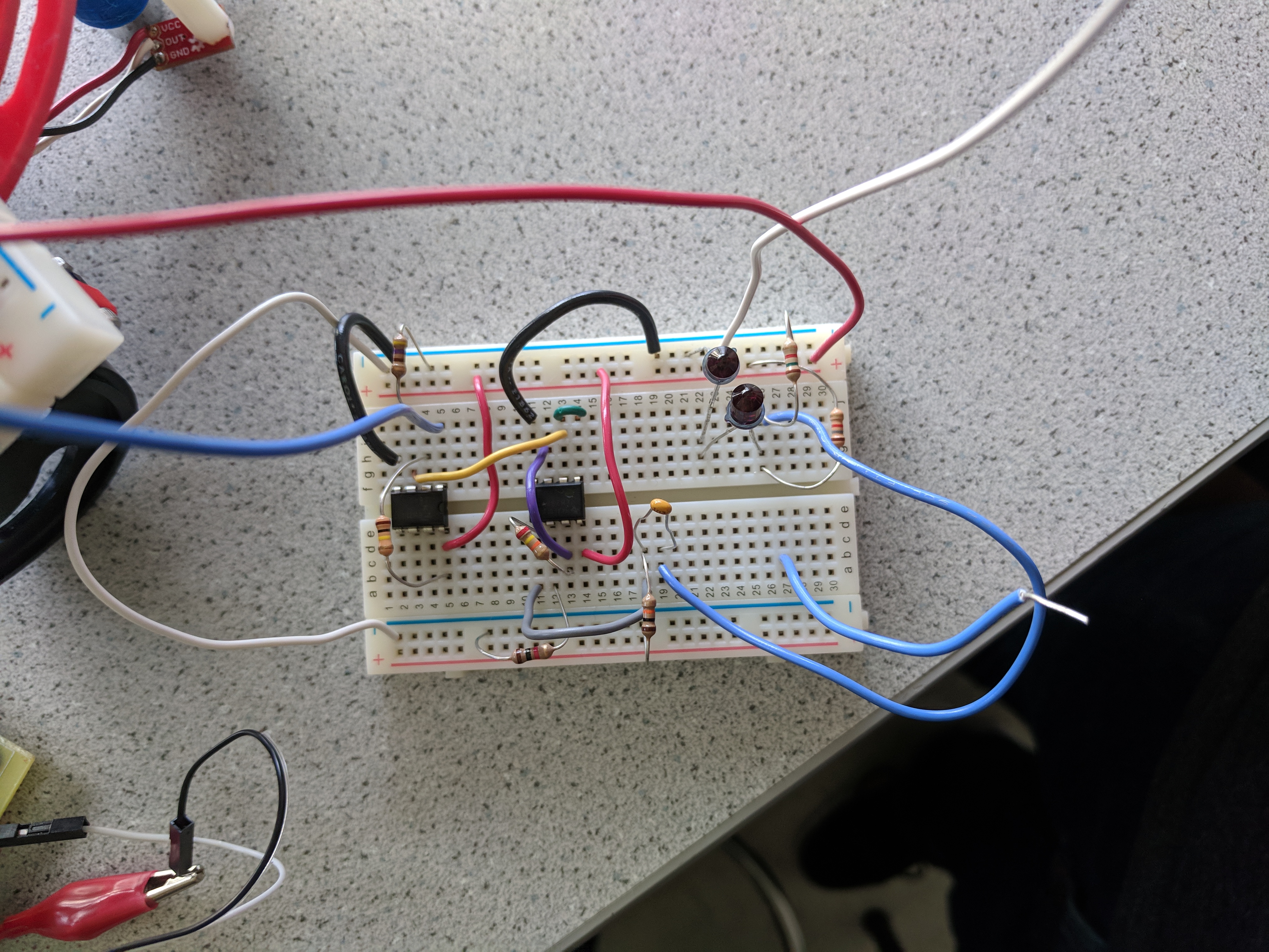
Overall our circuit for detecting other robots can be broken down into 3 stages. A picture of our completed IR circuit is below. You can see that one the top right of the image, there exist two phototransistors in series. That then feeds into the op-amp ICs, and the output commes out of the light blue wire which goes off-screen to the left.
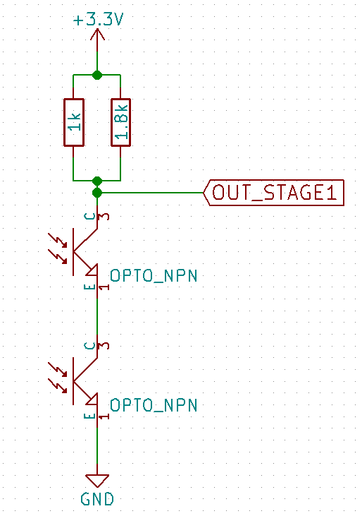
The first stage of our circuit is similar to the suggested circuit in the lab 2 handout. However, rather we chose to use two resistors in parallel and two phototransistors in series to increase the amplitude of the produced signal. Figure 1 shows this stage of the circuit. As the output of our circuit ranged from 20mVpp to 100mVpp at very close distances, we decided to amplify the output of this stage to increase the distance we can detect other robots from.
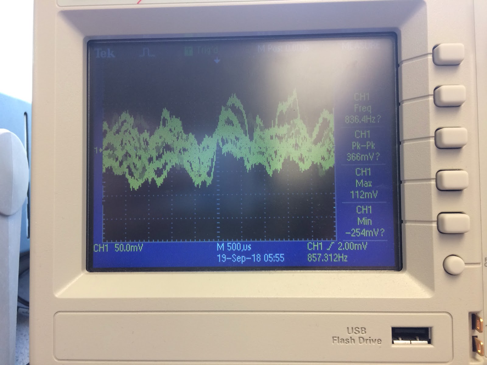
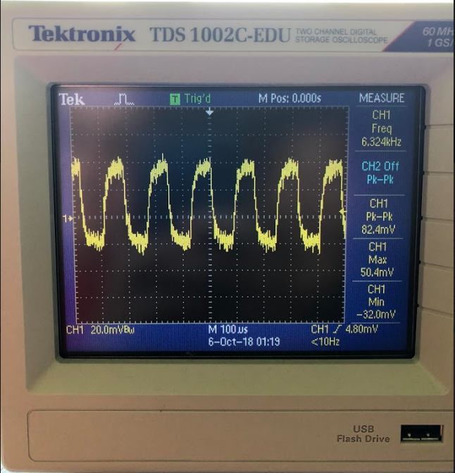
Once we implemented the output capture circuit, we probed the output of the first stage with an oscilloscope when holding a treasure close to the phototransistors. The treasures were tunable in frequency, so we were able to output both a 6.2kHz signal and a 18kHz signal, which approximate the frequencies emitted by the other robots and the decoy robots in the maze respectively. While there is a visible signal, its peak-to-peak voltage is very small, meaning that the Arduino would not easily be able to tell when the signal was present. In addition, in order to even get this clear of a signal, we needed to hold the IR source very close to the phototransistors, which would not be a viable solution for detecting robots from several inches away. We needed to add analog amplification.
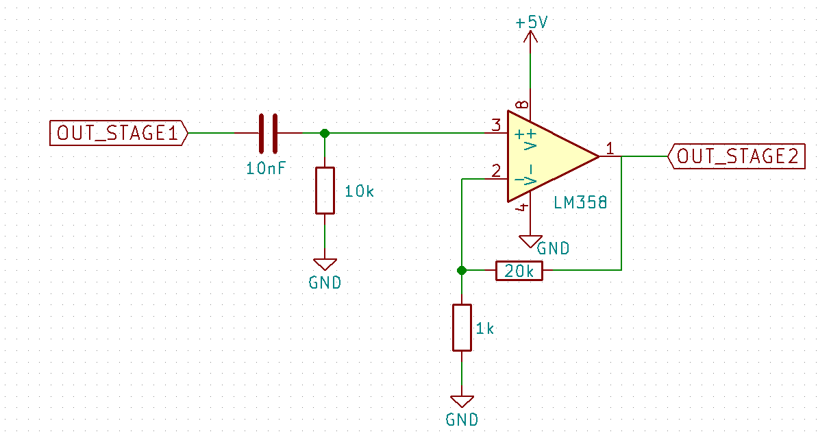
This stage is responsible for amplifying the output of our IR capture circuit. The circuit itself can be seen in figure 2 below. It should be noted that the output of the IR capture circuit has a DC bias of approximately 2.5V. Since we plan to have 20x gain, this would mean our signal would always hit the max voltage of 5V and would appear to be a constant high signal. Thus, to remove this bias we implemented a high pass RC filter using a 10k resistor and 10nF capacitor which has a cutoff frequency of roughly 1592Hz.
We then fed the output of the low pass filter into a non-inverting amplifier. We used a 20k resistor and 1k resistor set up in a negative feedback loop to achieve a gain of roughly 20x. We found that this amplification level gave us the clearest results on our output.
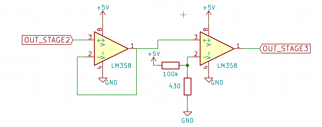
In order to further amplify our output, we fed the output of the amplification circuit to a comparator circuit, which we hoped would further increase the gain of our circuit and improve the signal quality. We first sent the input through a unity gain voltage buffer which ensured that as we experimented with different types of amplifiers and comparator circuits, the gain of each would act independently. With our final design, we no longer need the unity gain amplifier and may remove it to compact our circuit.
The second half uses a comparator with a voltage generated with a voltage divider. We first determined a voltage that we wanted to compare against by stepping through voltage levels on a DC power supply until the desired result was achieved. We found that we were able to get the clearest signal from the greatest range of distances for the IR treasure for a comparator reference voltage of approximately 23mV. The values of the resistors in the voltage divider were then determined to approximate that voltage, since 5V * (430/100000) = 21.5mV.
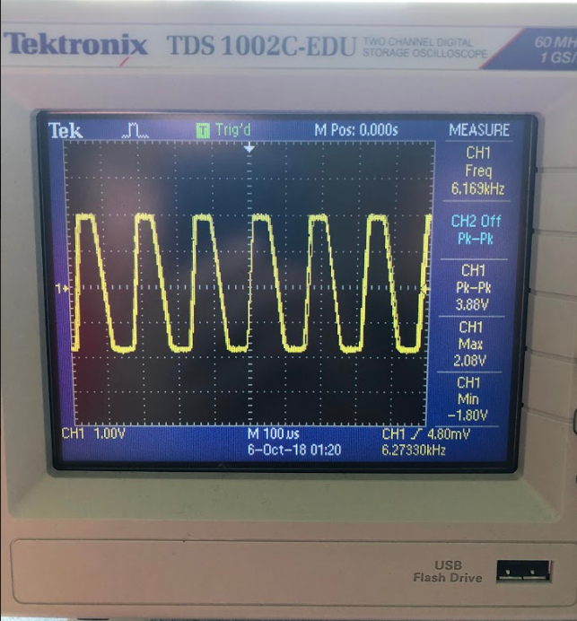
With the new amplifier and comparator, we were able to achieve the following output even when the IR emitter treasure was held 3-4 inches away from the phototransistors.
Once we had a high signal-to-noise ratio and a clear signal, we now wanted to
be able to read data into the Arduino and process the inputs to determine the
frequencies coming in. To do this we connected the output of our comparator
circuit to pin A0 of the arduino. We then used adc0 to read in the output of
the comparator circuit from the ADCL and ADCH registers and converted these
values into a single 16 bit integer. These values were then stored in the
fft_input array which was then used by the fft library to calculate the
magnitude of each bin. The graph below shows the result of this operation
for a 6kHz and 18kHz signal.
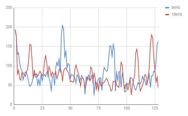
As can be seen, the peak magnitude of the 6kHz signal is around bin 40. This result is relatively accurate as our base clock for the arduino is 16MHz with an ADC clock prescaler of 32. As each ADC read takes 13 clock cycles this results in a sampling frequency of 38461.53. As we take 256 samples this means that each bin represents 150.24 Hz. If we divide 6.08kHz by 150.24Hz we find that the peak of our 6kHz single should be in bin 40 which is what we found.
We then use this information to determine when a 6kHz signal is present by checking to see if the magnitude of bins 38 - 44 are above 150. We decided to use 150 as our threshold since general noise did not seem to create peaks above 75 and the 18kHz signal also does not generate peaks in that range above 100. By checking a range of bins we are able to determine if an approximate 6kHz signal is present while having some tolerance incase the frequency is not exact. The code, which is inside of a loop, is as follows:
cli();  // UDRE interrupt slows this way down on arduino1.0 so we disable interrupts

// save 256 samples
for (int i = 0 ; i < 512 ; i += 2) {
  while(!(ADCSRA & 0x10)); // wait for adc to be ready
  ADCSRA = 0xf5; // restart adc
  byte m = ADCL; // fetch adc data
  byte j = ADCH;
  int k = (j << 8) | m; // form into an int
  k -= 0x0200; // form into a signed int
  k <<= 6; // form into a 16b signed int
  fft_input[i] = k; // put real data into even bins
  fft_input[i+1] = 0; // set odd bins to 0
}

// process FFT data
fft_window(); // window the data for better frequency response
fft_reorder(); // reorder the data before doing the fft
fft_run(); // process the data in the fft
fft_mag_log(); // take the output of the fft

sei(); // re-enable interrupts
Serial.println("start");
for (byte i = 0 ; i < FFT_N/2 ; i++) {
  Serial.println(fft_log_out[i]); // send out the data for off-chip processing
}
delay(1000);
for (int j = 38; j < 44; ++j) {
  if (fft_log_out[j] >= 150){
    digitalWrite(LED_BUILTIN, HIGH);   // turn the LED on (HIGH is the voltage level)
    delay(1000);                       // wait for a second
    digitalWrite(LED_BUILTIN, LOW);    // turn the LED off by making the voltage LOW
    delay(1000);                       // in reality, delay does not block other cmds so LEDs flash
  }
}
The results can be shown below.
We then combined the results of the IR team and the acoustic team into one larger project!
View Lab 2 Code on GitHub Close Project
In this lab we established a communication protocol between one Arduino, which will be on our robot, and another, which will remain at a base station and need to interface with a GUI to display the progress of our robot. This interface will also come in handy for debugging because we will be able to determine the progress of our robot and what it has discovered.
In order to communicate wirelessly, we used a pair of Nordic nRF24L01+ transceivers, as well as the relevant libraries. (can be found here)
We use the following two variables to store the current location of our robot:
uint8_t x = 0; // stores the x index/coordinate
uint8_t y = 0; // stores the y index/coordinate
We use the following 2-D array to store what we discover about each tile of the maze:
uint8_t maze[9][9] = {...};
We have also defined a set of macros that help us easily construct the correct bit sequence that describes what our robot sees, based on our protocol:
// walls
#define bm_wall       15 << 0
#define bm_wall_east  1 << 1
#define bm_wall_north 1 << 3
#define bm_wall_west  1 << 0
#define bm_wall_south 1 << 2

// treasure
#define treasure_shift 4
#define bm_treasure_none     0 << 4
#define bm_treasure_b_sq     1 << 4
#define bm_treasure_r_sq     2 << 4
#define bm_treasure_b_ci     3 << 4
#define bm_treasure_r_ci     4 << 4
#define bm_treasure_b_tr     5 << 4
#define bm_treasure_r_tr     6 << 4

// whether square explored
#define bm_explored     1 << 7
#define bm_not_explored 0 << 7
#define explored_shift  7

// presence of other robot
#define bm_robot    1 << 1
#define bm_no_robot 0 << 1
#define robot_shift 1
We learned that the maximum package the Nordic Radio module can send is 32 bytes, but we realized we only need to send 2 bytes of data to fully describe each tile, which means we were able to use a single transmission/packet per tile/cell. The following image describes the structure of our protocol:
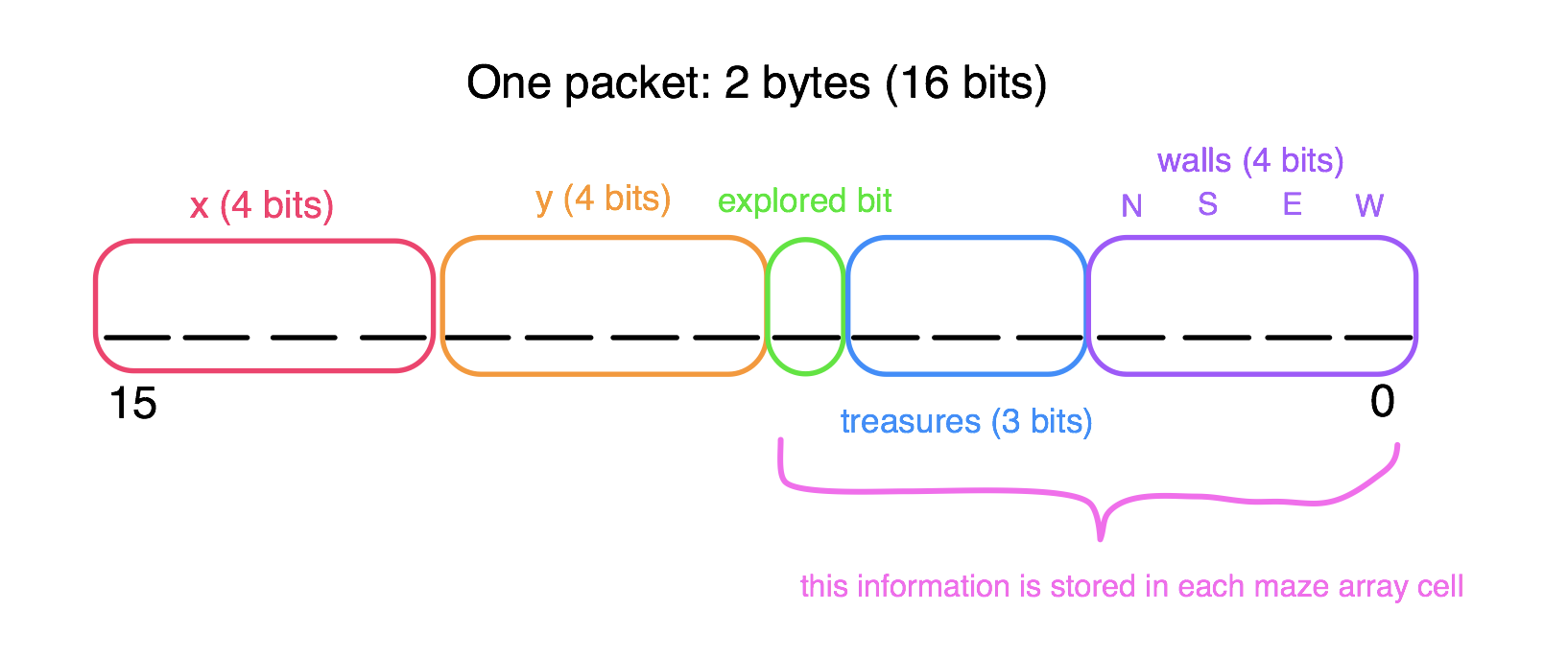
We believe that this protocol provides sufficient information about the state of the board. It includes the x and y coordinates of the current tile, which has just been explored. The explored bit is mainly for the robot itself to know if it has explored a tile. The treasure bits represent one of seven options: no treasure, blue square, red square, blue circle, red circle, blue triangle, and red triangle. Lastly, the for the bits representing each wall (north, south, east, west), a 1 represents that the wall is present in this tile and a 0 means it isn’t there.
We wrote a program to make a virtual robot explore a 9x9 maze with preset walls and treasures in order to test our radio communication and our protocol. We hard-coded the robot’s sequence of exploration for ease- it just snakes around the maze, as there is only one path anyway. We set the role of the virtual robot to “role_ping_out”, a.k.a. the transmitter, and we set the other Arduino to “role_pong_back”, or the receiver.
The following is our setup code, which is very similar to the setup found in the GettingStarted sketch in the RF24 Arduino library:
void setup(void) {
  // Print preamble
  Serial.begin(9600);
  printf_begin();
  printf("\n\rRF24/examples/GettingStarted/\n\r");
  printf("ROLE: %s\n\r",role_friendly_name[role]);
  printf("*** PRESS 'T' to begin transmitting to the other node\n\r");

  // Setup and configure rf radio
  radio.begin();
  radio.setRetries(15,15);
  radio.setAutoAck(true);
  radio.setChannel(0x50);
  // set the power
  radio.setPALevel(RF24_PA_HIGH);
  radio.setDataRate(RF24_250KBPS);

  // optionally, reduce the payload size.  seems to
  // improve reliability
  radio.setPayloadSize(2); // we only need 2 bytes

  // Open pipes to other nodes for communication
  // This simple sketch opens two pipes for these two nodes to communicate
  // back and forth.
  // Open 'our' pipe for writing
  // Open the 'other' pipe for reading, in position #1 (we can have up to 5 pipes open for reading)
  radio.openWritingPipe(pipes[0]);
  radio.openReadingPipe(1,pipes[1]);

  // Start listening
  radio.startListening();

  // Dump the configuration of the rf unit for debugging
  radio.printDetails();
}
Then, in the loop, we first develop the message that we are trying to send using the current cell information and the current location. We also print the message in binary for debugging:
uint8_t cell = maze[x][y]; // information about the current location, which our robot will use its sensors to determine
uint16_t coordinate = x << 4 | y; // generate the left byte of information (coordinates)
uint16_t message = coordinate << 8 | cell; // generate the whole message
Serial.println(message, BIN);
The rest of the communication code is the same as in the GettingStarted sketch, but we changed what happens when the response is received- if a good response is received, we then let the robot move to the next tile, but if no response is received (timeout), then the robot stays put and tries again in the next iteration. This way no information is lost. The code is below:
// Describe the results
if ( timeout )
{
  printf("Failed, response timed out.\n\r");
}
else
{
  // Grab the response, compare, and send to debugging spew
  unsigned long got_time;
  radio.read( &got_time, sizeof(unsigned long) );

  // Spew it
  printf("Got response %lu, round-trip delay: %lu\n\r",got_time,millis()-got_time);

  if (x == 8 && y == 8) {
      x = 0;
      y = 0;
  }
  else if (x%2 == 0){
      if (y == 8) x++;
      else y++;
  }
  else{
      if (y == 0) x++;
      else y--;
  }
}

 // Try again 1s later
delay(1000);
We wrote another program to be the receiver of the messages and to update the GUI. The setup is largely the same as the transmitter program, so we will only show the looping code. It receives a packet and then proceeds to decode it using bitwise operators and our macros, and then sends the information in the correct format to the GUI (location, walls, and treasures, then a new line). Lastly, it resumes listening for a new packet.
// if there is data ready
if ( radio.available() )
{
  // Dump the payloads until we've gotten everything
  uint16_t message;
  unsigned char coord;
  unsigned char walls;
  bool done = false;
  while (!done)
  {
    // Fetch the payload, and see if this was the last one.
    // spew out payloads
    done = radio.read( &message, sizeof(uint16_t) );

    int x = (message & (15 << xcoord_shift)) >> xcoord_shift;
    int y = (message & (15 << ycoord_shift)) >> ycoord_shift;
    bool north = message & bm_wall_north;
    bool south = message & bm_wall_south;
    bool east = message & bm_wall_east;
    bool west = message & bm_wall_west;
    uint8_t treasure = (message & bm_treasure);
    char buff[30];
    sprintf(buff, "%d,%d", x, y);
    Serial.print(buff);

    /*
     * Code for checking the message with each wall/treasure bitmask goes here
     * If a match is found, more is printed to Serial
     */

    // Ends printed message to GUI
    Serial.print("\n");

    // Delay just a little bit to let the other unit
    // make the transition to receiver
    delay(20);

  }

  // First, stop listening so we can talk
  radio.stopListening();

  // Send the final one back.
  radio.write( &coord, sizeof(unsigned long) );
  //printf("Sent response.\n\r");

  // Now, resume listening so we catch the next packets.
  radio.startListening();
}
This is the final result of using our virtual robot to wirelessly update the GUI!
The goal for this part of the lab was to integrate all of our robot’s sensing components, including recognizing the start signal of 660Hz with a microphone, line following, right-hand wall following, and detecting other robots while ignoring decoys. All of these features have been successfully built in previous labs/milestones, and so now we’ve integrated all of these features to prove that they can work together without interfering with each other.
Integrating all of our separate circuits and systems in order to complete lab 3 turned out to be more of a challenge than initially anticipated. For starters, our IR detection circuit, microphone circuit, sensor inputs, and servo controls all existed either on different breadboards or very far away from the arduino. This created a large mess of wires that made modifying and debugging our circuits difficult as every modification almost always resulted in accidently removing another wire.
Cleaning up, we moved all of our circuitry to two half-breadboards which we mounted on the top level of our robot, with our arduino now being mounted on the lower level. This gave us better access to all of our circuitry as well as it helped to reduce the nest of wires making our robot easier to debug and cleaner looking as well. However, as we re-wired out inputs and outputs from our arduino we ran into the problem that we had more analog inputs than the arduino could handle.
To get around this problem, we used the CD74HC4051 analog multiplexer to switch between our wall sensors, since we only needed to be able to read from those sensors fairly infrequently. As we currently only needed to mux between two inputs we grounded the S1 and S2 selection inputs and connected digital pin 7 of our arduino to S0 of the mux. We then connected the output channel of the mux to analog input pin A5.
A rather unanticipated issue that arose from using the mux was that both of our sensors appeared to be changing based off of the values from the right one. At first we believed that one of the sensors was simply broken since the mux had been functioning originally. However, we discovered that the mux does not sit properly in the breadboard, causing some of the pins to not be fully connected. This resulted in only one of the wall sensors ever being read. To fix this problem we needed to bend several of the pins in order to better fit the breadboard.
Another unanticipated problem we faced was the noise on our 5V rails caused by the wall sensors. Due to this noise our IR and microphone circuits ceased to function correctly. Our initial solution to this problem was to add as many decoupling capacitors as possible but we found that this simply didn’t work well enough. Instead, we decided to use the provided 5-to-3.3 voltage regulator, in order to have a separate power line dedicated to the sensitive IR circuit.
Finally, in order to integrate the maze GUI code with the robot maneuvering, we needed to keep track of the current orientation of the robot (which would get updated whenever we turn left/right), as well as update the internal maze state whenever we reach an intersection, at which point we are able to detect walls. Note that since we only broadcast the maze state one time, before it has been explored, some of the walls do not appear. This will be fixed once add a third wall sensor on the left side of the robot, so that we will be able to detect all of the walls at the same time.
First, we incorporated radio communication into our overall program, as shown in the video below. As you can see in the video, the robot now pauses for a bit at every intersection. We do this because this is when the robot broadcasts to the base station, and if the broadcast is unsuccessful, it stays put and keeps trying. The coordinates received in the base station are correct at every intersection, based on the starting coordinate of the robot being set to (0, 0). We did not show the actual GUI updating in this video, because it was inconvenient at the time of recording and we've already shown above that it works.
Finally, the following video shows everything incorporated into our robot (line following, wall following, radio communication, GUI, starting on 660Hz, responding to other robots, and ignoring decoys):
This last video shows the same robot (running the same code) detecting the IR hat from a farther distance.
At this point, we want to begin being able to detect visual treasures. Specifically, we need to be able to distinguish normal white walls from specific colored shapes attached to the walls. The treasures can be either blue or red, and can be any of a square, triangle, or diamond. In order to do this, we add a camera (the OV7670). The camera outputs data to an FPGA (the DE0-NANO), which then processes the image in real time in order to determine the presence or absence of any treasures, as well as what color they are. For debugging purposes, we also connected the FPGA to a VGA adaptor and monitor. A datasheet for the OV7670 camera can be found here. Note that since we deal with a field-programmable gate array, we now need to assign these register conenections in a hardware description language. We chose to write in Verilog compiled in Altera's Quartus Prime Lite softare.

Above is the visual of the specific types of treasures we wish to detect and differentiate. The graphic was borrowed from the ECE 3400 Fall 2018 course website.
Before we start, we want to get an idea of what types of images we can store and process in real time, since we need to be able to quickly determine whether or not there is a treasure while still navigating through a maze. The DE0-Nano has 594 Kbits of embedded memory, and each entry in the RAM must have a size of 8 or 9 bits. Assuming 8-bit entries, that leads to a maximum buffer size of 74250 entries.
To start, we wanted to get data quickly from the camera while maintaining the most color accuracy possible, so we receive RGB 565 data from the camera. The format for RGB 565 is below, with the MSByte being sent first by the camera, followed by the LSByte.
Note however that VGA cables require data in a RGB 332 format, which is shown above. This means that we must downsample the given camera data. That is, in order to keep the most important data from the RGB 565 information but fit it into a single bit, we only keep the most significant bits of each of the red, green, and blue channel to feed to the monitor for display.
Since we want to be able to take advantage of large-scale features of the image, and have less use for specific details, we choose to maintain a fairly small image size: we chose to use the smallest supported resolution of QCIF at 176x144 pixels. Many of the other settings were discovered through a series of trial-and-error experiments.
The camera team's goal was to communicate to the camera in order to adjust settings to the parameters determined above. The camera team also needed to have some fake-treasure data arising from the FPGA which would test the capability of FPGA to Arduino communication. The details of this communication are detailed in the final integration section of this page.
To communicate with the camera, we use the Inter-Integrated Circuit protocol, also called I2C or the two-wire interface I2C. To do this, we use the dedicated I2C pins on the Arduino Uno, the SCL for clock and SDA for data. There are a number of intricacies to I2C, but Wire Arduino library makes reading and writing fairly easy. Simplified example code to read or write to a specific register is below. The master device, in our case the Uno, sets the clock speed on the SCL line at that rate. The master's message is then sent synchronously over SDA and acknowledged by the slave, and responses are requested by the master as necessary.
byte read_register_value(int register_address){
  byte data = 0;
  Wire.beginTransmission(OV7670_I2C_ADDRESS);
  Wire.write(register_address);
  Wire.endTransmission();
  Wire.requestFrom(OV7670_I2C_ADDRESS,1);
  while(Wire.available()<1);
  return Wire.read();
}

int OV7670_write_register(int reg_address, *byte data){{
    int error;
    Wire.beginTransmission(OV7670_I2C_ADDRESS);
    Wire.write(start);
    Wire.write(&Data, 1);
    error = Wire.endTransmission(true);
    if(error != 0){
      return 0;
    }
    return 1;
 }
For the OV7670, the registers we can read and write determine important details of the camera operation, including the clock source, the output format, and gain and white balancing settings. In particular, we took care to write to the following registers:
Above is a video of the Uno communicating with the OV7670, reading a list of registers, writing to a subset of them, and then reading the same list of registers in order to confirm that the changes desired were implemented correctly. A complete list of the registers written to can be found in the code. For more information about the register specifics, see the datasheet linked above.
Another critical part of communicating with the camera was the generation of a 24 megahertz clock signal. In order to do this we use a phase locked loop generated by the fpga. We then use the output of the fpga as an input to the camera. More details can be found at the lab website.
This team's goal was to be able to store data coming in from the camera or some other source, and then display it onto a monitor through VGA.
To do this, we generated 25 and 50 megahertz signals using PLL in order to store and read data from the generated RAM at high rates. Since the camera pixel color data came over two bytes but the camera pins only supported eight bits in parallel, we needed to track whether we were reading in the most significant byte or least significant byte of each pixel and downsample specific bits of that color data accordingly before it was stored in RAM. Note that the camera also outputs synchronization signals, vsync and href, which help the fpga find the start and end of a row or frame, but we found the signals tended to be noisy so we required a transmission to be fairly clean by tracking the readings over several cycles and requiring a specific pattern.
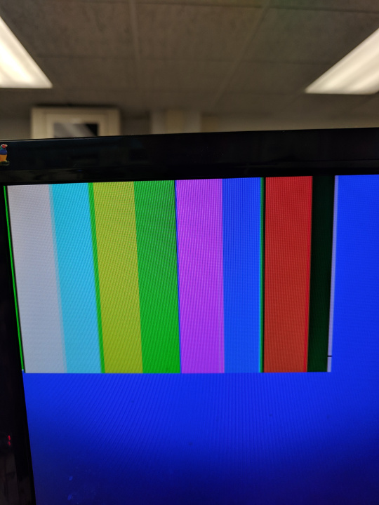
The FPGA reads from the stored camera data on each clock cycle and outputs it to VGA alongside other signals determined by the horizontal and vertical positions of the pixels being displayed. We started by manually writing to the FPGA memory in the program, followed by testing communication with the camera and the use of downsampling by displaying a color bar test from the camera, which can be seen below. Note that we used a solid blue color background in order to differentiate the smaller camera/memory output from the static background display pixels.
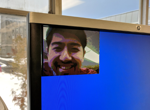
One we were confident in our downsampling and camera stability, we were able to capture life-like images on the screen from the camera, after more experimentation with color and gain settings. An example can be seen below.
We generated estimates of whether each pixel was either red, blue, or neither based off of simple thresholding of pixel values, in order to help determine whether an image being read from memory contained a red or blue treasure. For instance, blue treasures tended to appear dark blue or black to our camera, so we required that the red, blue, and green bits all be fairly low to label a pixel blue. On the other hand, red pixels had a lower bound threshold for the red values, as well as other bands for the blue and green values. These bounds were experimentally determined in order to maximize the chance that treasures could be separated from their backgrounds and each other in a variety of different lighting conditions. A simplified version of our code is below.
// PIXEL_IN from RAM, PIXEL_OUT_C goes to VGA
if (PIXEL_IN[1:0] <= 2'b10 && PIXEL_IN[4:2] < 3'b101 && PIXEL_IN[7:5] < 3'b101) begin
  // all fields dark - what tends to be blue
  blue_cnt = blue_cnt + 24'b1;
  PIXEL_OUT_C = 8'b000_000_11;
end
if (PIXEL_IN[7:5] >= 3'b010 && PIXEL_IN[4:2] < 3'b101 && PIXEL_IN[1:0] <= 2'b10) begin
  // anything somewhat red and not too green / bright
  red_cnt = red_cnt + 24'b1;
  PIXEL_OUT_C = 8'b111_000_00;
end
To more easily debug which pixels were believed were to be red, blue, or otherwise, we modified the VGA output to display a solid red pixel for red-thresholded pixels, blue for blue-thresholded, and black for other. We also found that sometimes, white pixels were being thresholded as red, so we generated a third category in order to show pixels the FPGA believed to be white, and therefore should not be counted as red. A video of camera footage post-processing can be seen below.
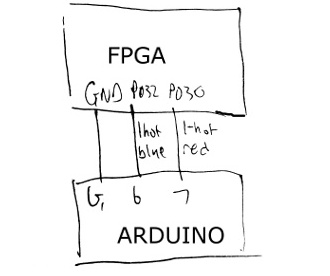
We then counted the number of red or blue pixels in a single frame. If the number of red pixels, for example, exceeded another experimentally determined threshold, we would say that the image most likely contains a red treasure. This information was then communicated to the Arduino a pair of output pins which were connected to Arduino GPIO pins. We demonstrate the color detection capabilities with a program which simply writes all of the necessary registers on the camera, and then constantly polls the FPGA-to-Arduino pins in order to determine what the FPGA believes the current state of the presence of treasures is. A video of this code in action can be found below. Since we continued to multiplex analog signals, we were able to utilize a pin-heavy parallel communication protocol.
Note that some of the code on the GitHub has been updated to include parts of our shape recognition algorithm, part of Milestone 4. Although some of the details have changed, the majority of the colored section code remains the same - the FPGA still counts the number of red or blue pixels in an image in order to different the dominant color and if there is a treasure or not. A video of the demonstration communicating with the Arduino and outputting results to the computer through its Serial port is below.
For more information, please take a look at the assignment page here.
Close ProjectThe goal of Milestone 1 was to add line tracking and maze traversing functionality to the robot in the absence of walls and treasures. The end goal was to have a robot capable of following a figure eight pattern on the ground. We added the following additional materials:
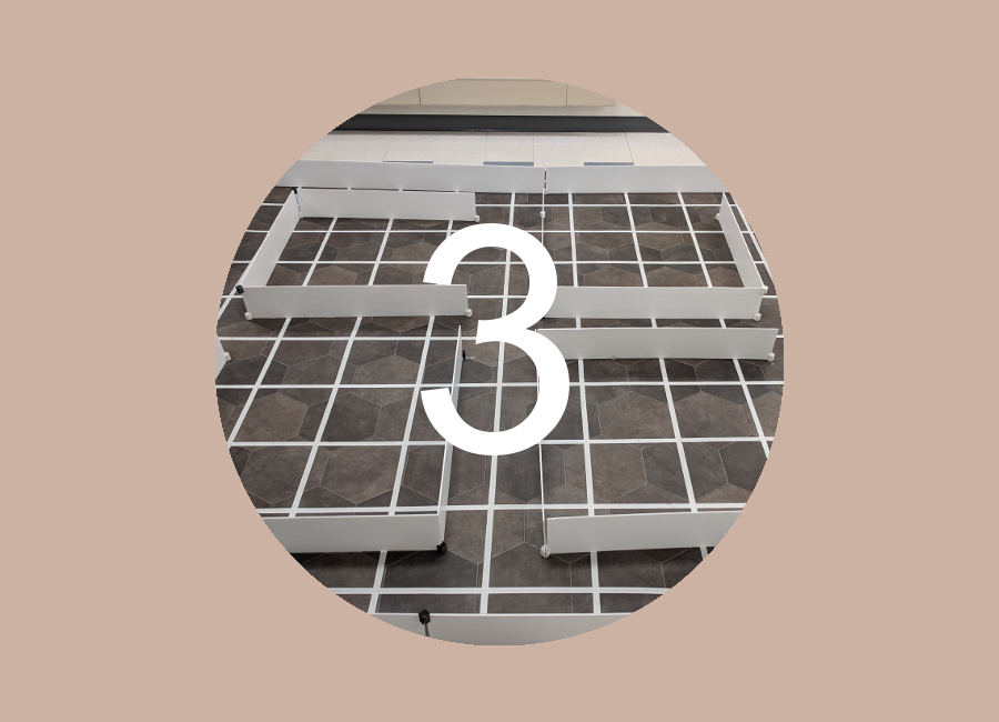
The robot needed to be able to navigate lines made of the electrical tape on a flat surface arranged in a grid pattern. In order to be able to detect where lines were on the ground, we used QRE1113 analog sensors. These were connected to an analog input pin on the Arduino which gave a value based on the reflectivity of nearby surfaces using IR, and were powered from the same 5V and GND powering the Arduino.
We then moved the line sensor above the ground surface at various heights and above both the taped line and the adjacent surface in order to discover some baseline values for what reflectivities mean what surface. We used those baseline values to determine a threshold, below which meant that the line sensor was on a line, and above which the opposite was true. We could now tell whether or not a line sensor on our robot was above a line!
We used three sensors (left, center, and right) to figure out where the robot was at any point in time. These sensors were placed at the front of the robot, spaced so that the distance between the left and right sensors is approximately the width of the line. The robot is considered centered when only the center sensor is on the line. When the left and center sensors are on the line, then the robot is veering slightly right, and we must turn slightly left. Similarly, when the right and center sensors are on the line, then the robot is veering slightly left and we must turn slightly right. If only the left sensor is on the line, then the robot is veering too much to the right and we must turn left more quickly. Similarly, if only the right sensor is on the line, the robot is veering too much to the left and we must turn right more quickly.
To detect an intersection, the analog value of each sensor is read using the analogRead function and then each value is compared to a light threshold. For example, when both the left AND right sensors read below the threshold value, meaning that both are directly above lines, we have determined that the robot is at an intersection and continue straight through the intersection in order to follow the line.
void loop() {
    // Our bot repeatedly moves forward then corrects itself
    forward();
    linefollow();
}

void forward(){
    // Moves the bot forward
    MotorLeft.write(83);
    MotorRight.write(95);
    delay(100);
}

void linefollow(){
    //Below 950 is white tape
    //Above 950 is dark
    LightDataC = analogRead(LightCenter);
    LightDataL = analogRead(LightLeft);
    LightDataR = analogRead(LightRight);
    if (LightDataC <= 950 && LightDataL > 950 && LightDataR > 950){
          // centered
          return;
    } else if (LightDataL <= 950 && LightDataR <= 950) {
          // intersection
          return;
    } else if (LightDataC <= 950 && LightDataL <= 950){
          // bot is veering right slightly, so we turn it left a bit
          MotorRight.write(92);
          MotorLeft.write(80);
          delay(400);
          return;
    } else if (LightDataC <= 950 && LightDataR <= 950){
          // bot is veering left slightly, so we turn it right a bit
          MotorRight.write(100);
          MotorLeft.write(88);
          delay(400);
          return;
    } else if (LightDataL <= 950){
          // bot is veering right a lot, so we turn it left more
          MotorRight.write(92);
          MotorLeft.write(80);
          delay(400);
          return;
    } else if (LightDataR <= 950){
          // bot is veering left a lot, so we turn it right more
          MotorRight.write(100);
          MotorLeft.write(88);
          delay(400);
          return;
    } else {
         // this case should never be reached!! if it does then y i k e s
    }
}
To accomplish a figure 8 we used our line following code to determine when we are at an intersection. Since all of our IR line sensors are in the front we then continued forward for an additional 350ms to ensure that we would begin turning when the robot is in the center of the intersection. Since we had to turn left and right in a complex pattern, we then referenced an array of integers using a global incrementing variable as the index. If the array was a 1 at that point then we would turn left, if it was 0 we would turn right. To accomplish the turn, we spun around for approximately 500ms and then finished the turn using a while loop which uses our line following code to detect when we have aligned with the line. Once the turn completed we incremented our global variable and continued forward until the next intersection.
At the top of our code, we initialized the following globals:
int turn[8] = {1,0,0,0,0,1,1,1};
int i = 0;
We added a push button on our robot so that it waits in setup() until we push the button:
// The following code is all in setup():
pinMode(8, INPUT);
...
while(digitalRead(8) !=  HIGH);
Our main loop moves the robot forward then corrects itself if necessary. While it's correcting itself, if it is at an intersection, it turns. We use turnRight() and turnLeft() as helper methods to turn the robot.
void loop() {
    // put your main code here, to run repeatedly:
    forward();
    linefollow();
    delay(20);
}

void turnRight(){
    MotorLeft.write(80);
    MotorRight.write(80);
    delay(600);
    while(!(LightDataC <= 775 && LightDataL > 775 && LightDataR > 775)){
      LightDataC = analogRead(LightCenter);
      LightDataL = analogRead(LightLeft);
      LightDataR = analogRead(LightRight);
    }
    MotorLeft.write(90);
    MotorRight.write(90);
    delay(100);
    return;
}

void turnLeft(){
    MotorLeft.write(100);
    MotorRight.write(100);
    delay(600);
      while(!(LightDataC <= 775 && LightDataL > 775 && LightDataR > 775)){
      LightDataC = analogRead(LightCenter);
      LightDataL = analogRead(LightLeft);
      LightDataR = analogRead(LightRight);
    }
    MotorLeft.write(90);
    MotorRight.write(90);
    delay(100);
    return;
}
The linefollow function follows the same pattern as before, but we now navigate at intersections as follows:
if (LightDataL <= 775 && LightDataR <= 775) {
  // Intersection
  digitalWrite(LED_BUILTIN, HIGH);
  forward();
  delay(350);
  if (turn[i] == 1){
      turnRight();
  }
  else turnLeft();
  if (i ==7){
    i = 0;
  }
  else {
        i = i + 1;
  }
  digitalWrite(LED_BUILTIN, LOW);
  return;
}
View Milestone 1 Code on GitHub
Close Milestone 1
The goal of Milestone 2 was to add right-hand wall-following and robot-detecting functionality to the robot while maintaining previously built line-tracking capabilities. To detect walls, we used IR distance sensors, one on the front of the robot and one on the right. We also added additional LEDs (in series with 330ohm resistors) in order to signal what the robot is thinking as it progress through the maze.
Many parts of our circuitry from previous labs and milestones were scattered across multiple breadboards and had to be powered by external power sources. Therefore, in order to have a contained drivable robot we needed to compactify our circuits and transfer them onto the main robot body. No major changes were made to either the IR detection or microphone circuit, although many of the specific pins we read have changed. We will continue to compact our circuit and make the connections more permanent/reliable throughout the rest of the lab sections. Note that for this milestone, we disconnect the microphone circuit entirely in order to make use of as many analog input pins as possible. In the future, we intend to free up analog inputs by replacing their usage with muxing or digital triggering circuits.
As shown in the video below, the red LED turns on when the robot senses a wall in front of it, and the green LED turns on when it senses a wall to the right. These LEDs only change at an intersection in the grid, because we only check for walls at these intersections. We determined a threshold value for the distance sensors by holding a wall a certain distance away from the robot so that we don't detect a wall too early or too late. Our right-hand wall-following logic is determined through a series of if-statements.
Firstly, in order to follow the wall to the right, we always want to turn right if there is no wall. Otherwise, if there is a wall to the right and no wall in front, we follow the wall forwards. Finally, if there are walls both the front and right, then we try to find a direction which does not have a wall in front by turning left. Each turn rotates the vehicle 90 degrees, so that once we know that there is no longer a wall both to the front and to the right, then there should be no wall to the front and we can continue driving forward. This allows us to reliably follow walls regardless of the configuration.
The following is commented code on how we implemented this:
// this is some code from our linefollow() method from Milestone 1 that we changed for this milestone
void linefollow(){
    //Below LIGHTTHRESHOLD is white tape
    //Above LIGHTTHRESHOLD is dark
    LightDataC = analogRead(LightCenter);
    LightDataL = analogRead(LightLeft);
    LightDataR = analogRead(LightRight);

    bool leftOnLine = LightDataL <= LIGHTTHRESHOLD;
    bool centerOnLine = LightDataC <= LIGHTTHRESHOLD;
    bool rightOnLine = LightDataR <= LIGHTTHRESHOLD;

    if (centerOnLine && !leftOnLine && !rightOnLine) {
        // centered
        Serial.println("Centered");
        return;
    } else if (leftOnLine && rightOnLine) {
        forward();
        delay(650); // this allows the robot to be centered on top of the intersection before turning
        wallfollow(); // new method!
        Serial.println("intersection");
        return;
    }
    ... // other cases
}

// our wall-following code
void wallfollow(){
  wallRight = analogRead(A5);
  wallFront = analogRead(A4);
  if (wallRight >= SOMETHRESHOLD) digitalWrite(rightWallLED, HIGH); else digitalWrite(rightWallLED, LOW);   // turn the right wall LED on
  if (wallFront >= SOMETHRESHOLD) digitalWrite(frontWallLED, HIGH); else digitalWrite(frontWallLED, LOW);   // turn the front wall LED on
  if (wallFront <= SOMETHRESHOLD && wallRight >= SOMETHRESHOLD) { // if greater than threshold there is a wall
      // following the right wall: we can go straight
      return;
  }
  if (wallRight <= SOMETHRESHOLD){  // nothing on the right, so we can turn right
      turnRight(); // turns right until the center line sensor hits a line
      return;
  }
  while (wallFront >= SOMETHRESHOLD && wallRight >= SOMETHRESHOLD){ // blocked on both front and right- keep turning until we aren't blocked
      turnLeft(); // turns left until the center line sensor hits a line
      wallRight = analogRead(A5);
      wallFront = analogRead(A4);
      // signal our findings with LED
      if (wallRight >= SOMETHRESHOLD) digitalWrite(rightWallLED, HIGH); else digitalWrite(rightWallLED, LOW);
      if (wallFront >= SOMETHRESHOLD) digitalWrite(frontWallLED, HIGH); else digitalWrite(frontWallLED, LOW);
  }
  return;
}
In order to be able to detect and avoid other robots, we needed to integrate the IR FFT detection with the other analog input reading that our Arduino does. However, we quickly found that the FFT detection code from Lab 2 changed some of the serial communication registers and timers, which results in servos behaving strangely or not moving at all. In order to get around this obstacle, we stored the state of the required registers and then restore them once the FFT is processed and we return: TIMSK0, ADCSRA, ADMUX, and DIDR0.
We also found in our testing that our robot was failing to reliably detect walls once powered off of the Arduino's 5V line, due to coupling with other components or the operations within the Arduino. This meant that a single reading from the IR FFT code was not sufficient to ascertain that a robot was present, but the sensing was also not reliable enough that we could count on every single reading returning that there was a robot present. Therefore, we needed to have some way of keeping track of how often we thought there was a robot present. We required that several readings detect the presence of a 6kHz IR source in quick succession by having count of the number of readings that increases when the FFT says there is a 6kHz peak, and otherwise slowly decays. Then, we only tried to avoid robots when the reading count was high enough. This essentially allows us to filter through the noise.
We then were able to reliably do line tracking, wall avoidance, and robot avoidance together.
The goal of Milestone 3 was to make our robot capable of complete maze exploration using a search algorithm (or a combination) from the following common algorithms: DFS, BFS, Dijkstra, or A* search. We decided to use a simple DFS for a more safe, easy-to-debug graph traversal after failing to incorporate a greedy search into our DFS due to problems with pointers, but we will continue to try incorporating the greedy search!
To quickly demonstrate the goal of this milestone, here is a quick video of our robot doing a DFS exploration on a small (3x2) grid:
Here is an image that gives an overview of how DFS works, taken from here:
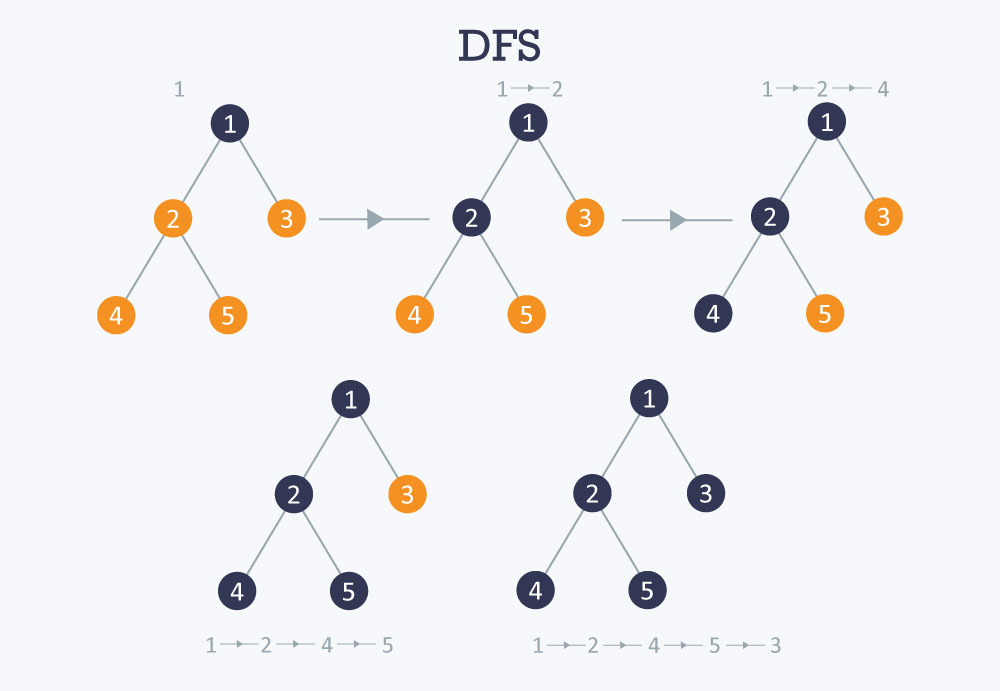
We use a recursive strategy for our DFS. At each location, we call dfs() on all the possible locations we can move to from the current location, so that they are all one step away in one of the four (N, S, E, W) directions. We only call dfs() on valid exploration locations, i.e. locations that are in the grid and have not been explored. This way we don't create an enormous call stack. Before we actually move to a location, we check if we shouldMove() (no walls blocking us).
The following code snippet illustrates our DFS algorithm:
StackArray<uint8_t> path; // maintains the current path

void dfs(uint8_t xCoor, uint8_t yCoor) { // xCoor and yCoor are the next location to move to, guaranteed to be one away, a valid location, and not explored
  if (shouldMove(xCoor, yCoor)) { // check if a wall is blocking our way- if so, we shouldn't move there.
    moveOne(xCoor, yCoor); // this function physically moves the robot one step to (xCoor, yCoor), updating the current location
    path.push(yCoor); // add the y coordinate to the stack (this is the current lcoation)
    path.push(xCoor); // add the x coordinate to the stack (this is the current lcoation)
    explore(); // old code that reads sensors to explore the location for walls and treasures
    if (explored == rows*columns){
      // we've explored the entire maze!
      while(1){
        // stops moving
        MotorLeft.write(90);
        MotorRight.write(90);
      }
    }
    // here we call dfs() recursively on the 4 possible ways to move, but only if it's a valid location
    // our call order for the 4 directions is different based on the current direction- we show one of our if-statements below
    if (current_dir == S) {
        // only call dfs() for locations that haven't been explored and are on the grid to minimize call stack
        if (maze[xCoor+1][yCoor] == 0 && xCoor+1 >= 0 && yCoor >= 0 && xCoor+1 < rows && yCoor < columns) {
          dfs(xCoor+1, yCoor);
        }
        if (maze[xCoor][yCoor-1] == 0 && xCoor >= 0 && yCoor-1 >= 0 && xCoor < rows && yCoor-1 < columns) {
          dfs(xCoor, yCoor-1);
        }
        if (maze[xCoor][yCoor+1] == 0 && xCoor >= 0 && yCoor+1 >= 0 && xCoor < rows && yCoor+1 < columns) {
          Serial.println("made it");
          dfs(xCoor, yCoor+1);
        }
        if (maze[xCoor-1][yCoor] == 0 && xCoor-1 >= 0 && yCoor >= 0 && xCoor-1 < rows && yCoor < columns) {
          dfs(xCoor-1, yCoor);
        }
    }
    // ... and so on, with a different order for each of the other 3 directions
    // at this point, if we get here, this means we hit a dead end, so we backtrack
    // remove current loc from stack
    path.pop();
    path.pop();
    // get the previous location to move to- just a peek
    uint8_t backX = path.pop();
    uint8_t backY = path.peek();
    path.push(backX);
    // move to the location- it is already guaranteed reachable
    moveOne(backX, backY);
  }
}
As seen above, to make our search easier to implement, we imported a library called StackArray to maintain a stack of our current path, which allows us to easily backtrack when we hit a dead end. All we do is pop the current location off the stack (we pop twice, once for the x-coordinate and once for the y-coordinate), and then peek at the next two coordinates to get the location we want to move to. The invariant is that the location we move to is always one step away and is physically reachable from the current location, i.e. there are no walls blocking our path.
We start the DFS in loop() by exploring the first (0, 0) location, then adding (0, 0) to the path stack, and then calling dfs() twice on the south and east locations, because those are the only two that are valid based on our starting location and direction (south). The code is below:
void loop() {
  explore();
  path.push(y);
  path.push(x);
  dfs(1, 0);
  uint8_t backX = path.pop();
  uint8_t backY = path.pop();
  moveOne(backX, backY); // move back to the starting location to branch to the other side of DFS
  dfs(0, 1);
  // we should have explored the entire maze at this point- this is just for debugging
  Serial.println("somehow finished");
  while(1){}
}
We've run this algorithm on two different 4x5 grids- one is more simple, one is quite complex. The following two videos show the results. One quick note is that in the videos, we correct the robot's course quite a few times due to the robot missing the lines (we filmed during sunrise so the light kept changing, and different parts of the maze were lighter than others). Even so, it is easy to prove that our algorithm is still correct, because once we put the robot on its intended path, it continues to explore smoothly, which means it knows where it is, and that indeed where we moved it is where it was intended to go.
The following are two videos of our robot updating the GUI as it explores the maze! The first video is a very small 3x2 maze to quickly show that the GUI works, and the second is the large 9x9 practice maze to show that the robot can complete the maze and correctly display the entire maze on the GUI. The GUI was implemented in Lab 3. Treasures are not included yet.
After many hours we were able to write a correct and working DFS & greedy algorithm, but unfortunately after trying the robot on large mazes (ones with >40 tiles) it started to reset itself due to lack of dynamic memory. Unable to condense our code any more, we decided that for the competition we would use our simple DFS, which is able to cover the entire maze for sure. This proved to be good enough for the competition, as we ended up winning first place!! :)
The goal of Milestone 4 was to add shape detection functionality to the robot, adding upon the progress made in Lab 4. In order to do this, we employed a number of different techniques, before settling upon generally using edge detection in order to determine the shape of the treasure. We use the same OV7670 and DE0-NANO from Lab 4, but with an updated communication protocol and different software.
As we continued to interface with the OV7670, we found that the camera tended to have streaking effects and visual artifacts. Although these were mitigable by image processing techniques, occasionally red shapes would appear entirely blue and vice versa, rendering our color detection algorithms useless. It is possible that the high speed (up to 24MHz) signals were above the actual Arduino or camera specifications and led to undefined behavior.
We found that switching our color data format from RGB 565 to RGB 444, in which each color field contains 4 bits of information, kept the same amount of color data once downsampled, but lead the much more stable and accurate color information. A snippet from the new downsampling algorithm is below.
if (CAM_COUNT == 1'b0)begin
  W_EN = 1'b0; // on the first cycle of a pixel - do not write!
  data[7:0] = CAM_DATA; // shift data from camera into LSByte
  CAM_COUNT = 1'b1; // next, we take in the MSByte data
  X_ADDR = X_ADDR;
end
else begin
  data[15:8] = CAM_DATA; // shift data from camera into MSByte
  CAM_COUNT = 1'b0; // next, go to LSByte

  downsampled[7:5] = data[11:9]; // downsample
  downsampled[4:2] = data[7:5]; // data takes form X R G B
  downsampled[1:0] = data[3:2]; // where each is 4 bits

  X_ADDR = X_ADDR + 1; // we now go to next address
  W_EN = 1'b1; // write downsampled to RAM
end
Reliably determining shape requires some form of comparative information - is there an edge at a particular location? Does the shape get wider or narrower as you move down across an image? To achieve accurate edge detection, we store pixel data for the current row as well as two previous rows of the image. In particular, we store whether or not we believed that a particular pixel was blue or red. This allows to determine the presence of the edge of a shape, as well as what direction the edge is in.
Since we store data from the previous three rows, we are able to search for matches with a 3x3 pixel pattern which represent an edge. In particular, we found that comparing with four particular patterns were useful in determining treasure shape. As seen in the snippet below, we look for approximately diagonal edge patterns in the pixels. A similar code snippet would check for red diagonal patterns.
// blue_recent contains 3x3 grid of pixel color data
case (blue_recent)
  9'b111_110_100: begin
    // upper left
    num_diag_u_b = num_diag_u_b + 12'd1;
  end
  9'b111_011_001: begin
    // upper right
    num_diag_u_b = num_diag_u_b + 12'd1;
  end
  9'b001_011_111: begin
    // bottom right
    num_diag_d_b = num_diag_d_b + 12'd1;
  end
  9'b100_110_111: begin
    // bottom left
    num_diag_d_b = num_diag_d_b + 12'd1;
  end
endcase
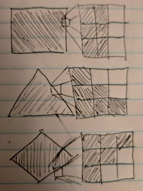
We then utilize this edge detection to differentiate between the shape types. In particular, slanted edges are a strong indicator of triangles and diamonds. As the diagram below indicates, triangles tend to have edge patterns with the colored pixels in the lower half, whereas diamonds are an even mix of upper and lower diagonals, and squares have very few of either. A predefined threshold would then separate noise from meaningful indicators of the presence of a triangle or diamond.
We also found that while our color and shape detection usually remained accurate, there were still frequent blips on the information received by the Arduino. We combatted this by adding simple low-pass filters over many of the counting signals inside of the image processor module. This averaging spreads out the effect of outlier frames and reducing the chance that the Arduino will randomly sample an output which does not accurately represent the shape that the FPGA tends to believe the shape is. One example assignment for a low pass filter is below.
num_diag_u_r_p = (num_diag_u_r_p - (num_diag_u_r_p >> 3) ) + (num_diag_u_r >> 3);
With the addition of treasure data, we now required a more advanced form of communication with the Arduino. We found that since we already had a 3-bit encoding for treasure data which was present in our Arduino GUI updating code and maze information storage, that it was natural to extend this to also be the format that the FPGA to Arduino communication took place. Instead of a pair of wires, now three wires run from the FPGA to the Arduino, each one being a bit in the three-bit treasure representation established in Lab 3. Below is the code running on the robot Arduino which reads the FPGA communication pins to determine treasure information.
  int FPGA_read = 0;

  FPGA_read += (digitalRead(FPGA_PIN_2) << 2);
  FPGA_read += (digitalRead(FPGA_PIN_1) << 1);
  FPGA_read += (digitalRead(FPGA_PIN_0) << 0);
  Serial.print(F("Received "));
  Serial.println(FPGA_read, BIN);

  switch (FPGA_read) {
    case 0:
      break;
    case 1:
      Serial.println(F("blue square"));
      break;
    case 2:
      Serial.println(F("red square"));
      break;
    case 3:
      Serial.println(F("blue dia"));
      break;
    case 4:
      Serial.println(F("red dia"));
      break;
    case 5:
      Serial.println(F("blue tr"));
      break;
    case 6:
      Serial.println(F("red tr"));
      break;
    default:
      Serial.println(F("Unknown"));
      break;
  }
Two videos below showcase the robust color and shape detection. The first runs through all six types of treasures present in the final maze, and the second displays the FPGA's ability to differentiate between having a treasure and not having a treasure.
Glenna Zhang, Liliet Sosa, Anthony Viego, Kevin Ying
Every person on the team will have to take the role as a leader. The role of the leader will be to organize meetings and make sure that everything is submitted in a timely manner. Please note here who will be responsible when:
Weeks 1&2: Kevin Ying
Weeks 3&4: Glenna Zhang
Weeks 5&6: Liliet Sosa
Weeks 7&8: Anthony Viego
Weeks 9&10: Glenna Zhang
Weeks 11&12: Liliet Sosa
Weeks 13&14: Kevin Ying
Weeks 15&16: Anthony Viego
A ban on offensive autonomous weapons would be beneficial to humanity without a doubt; however, it would ultimately not be very effective. These weapons are very cheap to make and they do not require hard-to-obtain materials (1). This means that although most scientists agree that such weapons would be detrimental to society, unsupervised groups, such as terrorist groups, could very easily develop and use their own autonomous weapons. To counter these types of attacks, the rest of society would be pushed to develop autonomous weapons as well. The ban would be a good start, but much work would need to be done to make it effective.
Furthermore, the definition of what weapons are included in this ban is unclear and allows for quite a grey area. The specific wording of the ban is weapons that do not have “meaningful human control” but one could argue that a facial recognition weapon has meaningful human control. As an example, a quadcopter with facial recognition could still be flown by a pilot and the target selected by the pilot, but the device simply locks onto the target once it is found and attacks. Even if the quadcopter chooses its target independently, a human must have programmed how to handle target selection, therefore adding human bias and a form of “human control” to the weapon’s algorithm. Additionally, it would not be hard for groups to simply conceal their research under another name or idea. Especially in the case of autonomous weapons and robotics it would be fairly easy for a group to claim they are working on a search/rescue vehicle but really developing the framework and infrastructure for an autonomous weapon.
While most countries are likely to follow the ban as can be seen in the case of the ban on chemical warfare, there are always countries that will ignore it. To rectify this issue a governing body would be needed to oversee the ban. The most likely candidate for this would be the UN’s ICJ. However, this organization works relatively slow and technological development is notably fast. To implement this ban correctly governments around the world would need to create individual bodies responsible for preventing the creation of such weapons. However, whether or not they will do so is unclear. Many will also attempt to make an argument similar to a “nuclear deterrent” in which everyone should have autonomous weapons, so no one uses them. Yet, in this case, that most likely will not work as nuclear bombs and autonomous weapons are in very different leagues and it is entirely possible for the use of autonomous weapons to even go unnoticed.
Overall, a ban on autonomous weapons is very difficult to implement since there are many factors that world leaders cannot control that would contribute to its ultimate failure.
Sources:
(1) "Autonomous Weapons: An Open Letter from AI & Robotics Researchers." https://futureoflife.org/open-letter-autonomous-weapons/?cn-reloaded=1
CloseThe goal of the class was to design and implement a fully autonomous robot capable of line following, wall detection, tone detection, IR detection, radio communication, avoidance of other robots, and complete maze exploration. It communicated its location and surroundings using an RF transceiver to an external GUI base station as it mapped the maze. The robot was also supposed to use a camera and FPGA to detect visual treasures in the maze, analyzing them for color and shape, but unfortunately, this was not integrated into the final system for reasons explained later. Our robot, the Angry Bot, performed all these tasks so well that it obliterated the competition and won first place!!
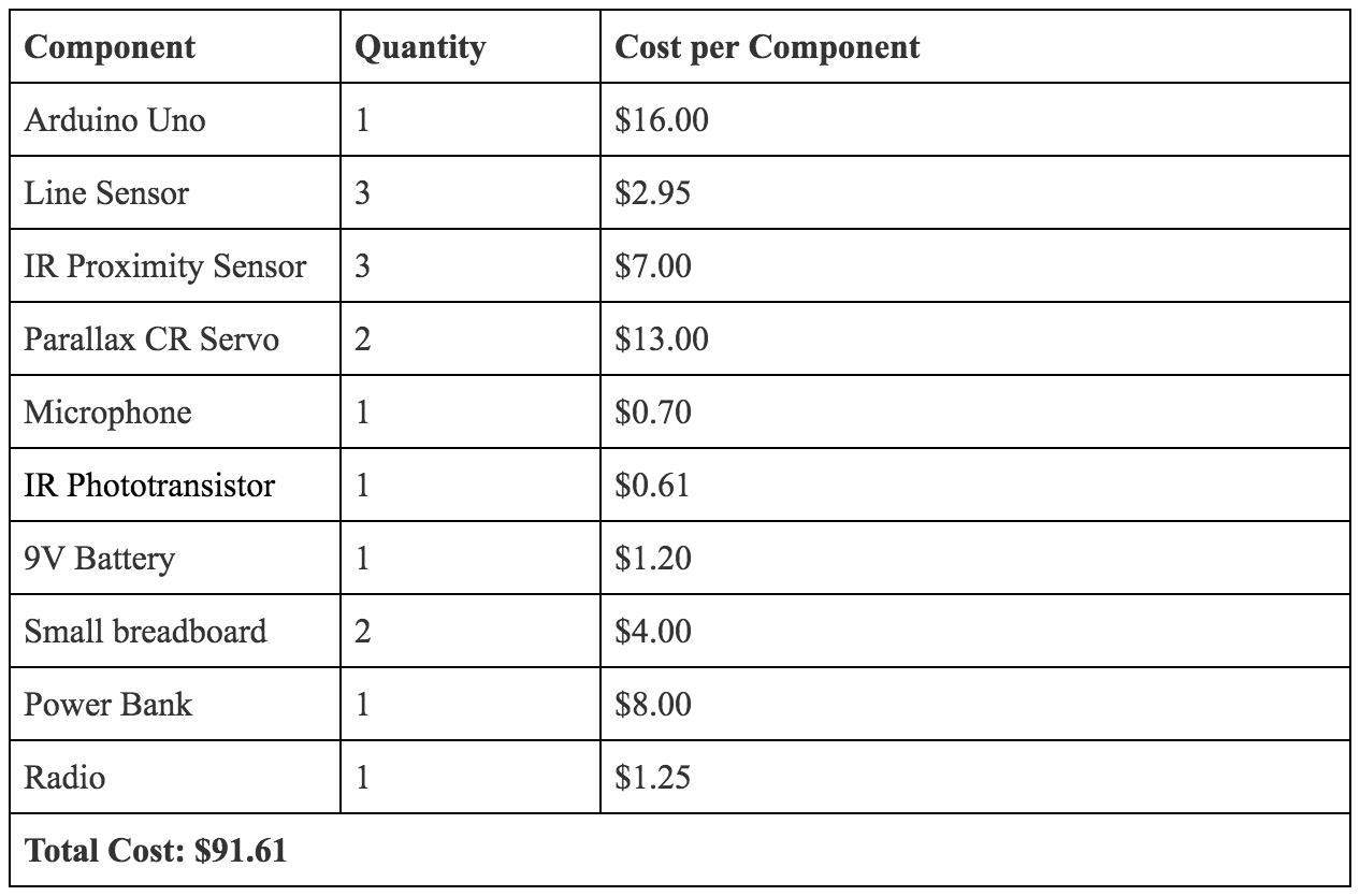
Not included in the cost include the provided IR hat, which allows other robots to detect our robot's presence, as well as various simple electronic components, such as wires, LEDs, op-amps, capacitors, and a small section of a perf board, which connected our robot together electrically. In addition, we used various mechanical components for which the cost can be difficult to estimate, such as the chassis, wheels, and 3D printed screws.
The robot also requires a base station to communicate to, which consists of:
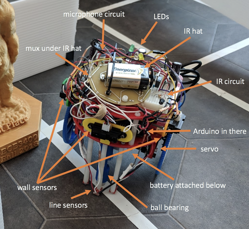
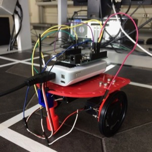
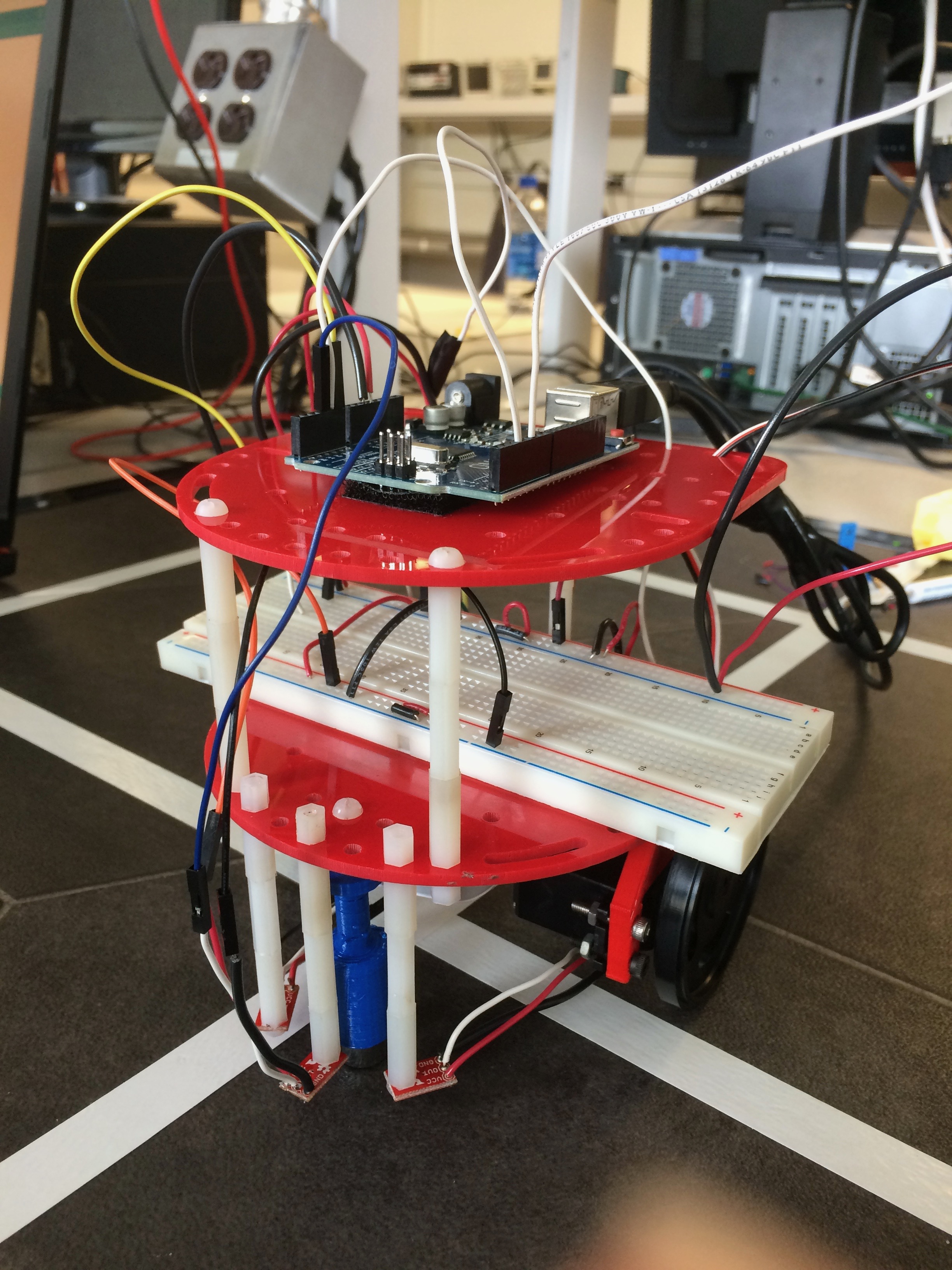
Generally, our robot consists of a laser-cut chassis, to which various sensors are mounted. Seen at the bottom front are our three line sensors, attached to 3D printed parts for stability. Behind that is a ball bearing for stability, the location of our velcro-attached battery pack (not pictured), and the pair of Parallax continuous rotation servos and accompanying wheels. On the middle layer of the robot lies our Arduino brains, the three wall sensors, and our radio transceiver. On the top layer, our microphone circuit, IR circuit, backup start button, and analog multiplexer. Not pictured is the IR hat needed for competition, or the new, larger blue wheels used in competition.
Line Sensors and Line Following
To successfully follow white lines on a dark surface, we mounted three line sensors (SparkFun QRE113 breakout boards) to the front of the robot, attaching them so that they were only a couple millimeters from the ground. We chose to use three sensors in order to be able to tell when we were on the line (using the center sensor), and if we were off of the line, then in which direction and by how far, depending on what combination of side and center sensors were still on the line. By placing these reflectivity sensors very close to the maze surface, we were able to achieve a stark contrast between light and dark surfaces: the analog input from light surfaces ranged between 0 to 70, while the values from dark surfaces ranged between around 700-900. This clean result easily allowed us to set a simple threshold for all the line sensors, which we placed at 400, so if a value read was below 400, the robot would think the sensor is on the line, and if it was higher, the robot would think the sensor is off the line.
We only made this greatly beneficial change a day before the competition- throughout the semester, our line sensors were slightly further from the ground, resulting in closer line-sensor output ranges and therefore less reliable line detection and line following.
A quick design note: because we ended up having so many analog inputs and not enough analog pins, we connected all our analog signals to an analog multiplexer, using two digital pins and an analog pin (because the radio and our debugging LEDs used up the other digital pins) to output select bits controlled by our code, and using an analog pin to read in the output of the mux. We wrote a neat little method called readMux() to go through the possible select bit patterns and read the analog values, storing each in its corresponding global variable that represents the signal connected to each mux channel. So whenever we wanted to read the values of the line sensors, for example, we just called readMux() and used the updated global variables to calculate if the robot was on the line or not.
To briefly describe how the line sensors work: they each have an IR emitting LED and an IR sensitive phototransistor to detect the IR light reflected back to the sensor. The analog output depends on the amount of reflected light- the more light reflected, the lower the output voltage to the board.
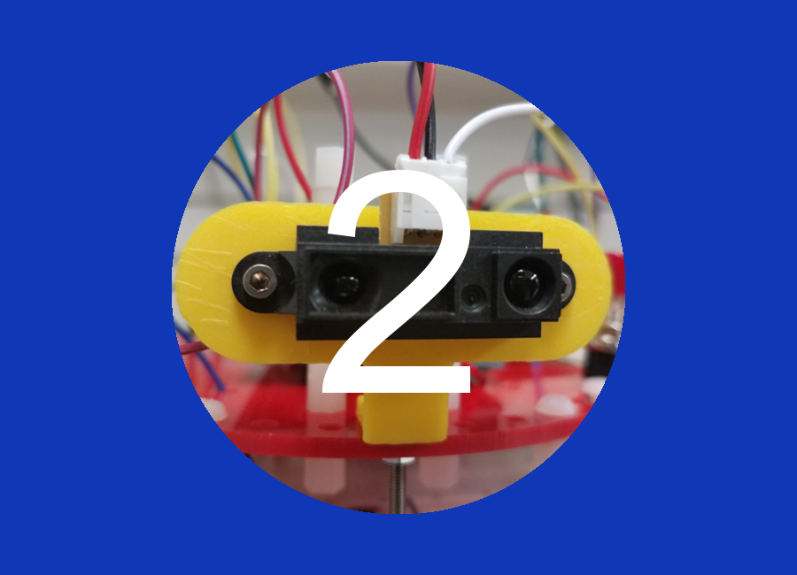
Wall sensors and Wall Detection
Our wall sensors are proximity sensors. They work by sending an IR signal at an angle. Assuming that the signal is received back from the wall, and that the angle of incidence equals the angle of reflection, the farther that the robot is from a wall, the more horizontal distance is between the emitting IR LED and the sensors that detect the returning signal. The wall sensors then report this distance as an analog voltage which our Arduino reads. This lets our robot detect walls in a color-independent way, since it is only measuring distance and not the intensity of the IR wall reflection.
We were then able to experimentally determine thresholds which determined whether a wall was present or not. We aimed to set the threshold at 4 to 6 inches away from the robot, as to leave little ambiguity if there was a wall or not. These wall sensors were then mounted onto a 3D printed mount, which was attached to the robot chassis with metal screws, such that they faced all three directions walls could be, forwards, left or right. We did not require a wall on the back of the robot, since when we explored a new square, we knew that there must not have been a wall behind us to allow us to arrive in that square.
We used three colored LEDs to represent whenever the robot detected a wall on each side. This made debugging much easier as we could see what the robot saw, and predict what it would do from there. We also wrote a nifty, separate Arduino sketch to test both the wall sensors and the line sensors, so that at the beginning of every lab/open lab, we would test our robot to make sure those basic features were working, saving us a great deal of time when debugging!
Microphone
Part of the competition is to start the robot automatically at a 660Hz signal. In order to do this, we added a microphone, which converts mechanical motion of an electromagnet into an electrical signal.
The output signal from just the provided microphone was too noisy, and so the correct 660 Hz frequency could not be identified using an FFT. The signal was also very small, making it harder to detect. Therefore, we decided it was necessary to put the microphone output through an active filter to low-pass and amplify the signal. We then used a voltage divider to center the voltage between 2.5V (because the Arduino’s I/O pins can only handle input voltages between 0 to 5V). The circuit design we used comes from the 2017 TA team’s solution (Team Alpha), so we’d like to thank them for this working solution! This gave us a nice signal that was later processed to determine if there was a peak frequency at 660Hz. We were then consistently detecting the 660 Hz signal that the Angry Bot used to start. This functionality was very reliable and helped Angry Bot start on-the-dot during the competition! We also included a pushbutton to start the robot upon restarts or if the microphone circuit failed.
Our signal processing also ended up being one of our greatest secret weapons. Instead of using the standard ArduinoFFT library, we instead used the similar ArduinoFHT library, which implements the Fast Hartley Transform, or FHT. The FHT is analogous to the Cooley-Tukey FFT algorithm, with the distinction that it transforms real inputs to real outputs, instead of handling complex data. This limitation became very useful, since the library only requires one byte per input or output data point, instead of two to store real and imaginary parts. This halved the global variable memory taken up by the FFT and allowed us to store the maze data and DFS stack separately without fear of running out of memory.
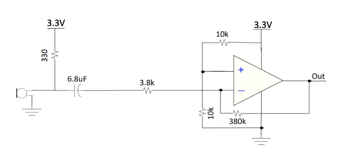
IR Detection (and IR Hat)
Another part of the competition was to be able to avoid other robots within the 9x9 maze in which we were exploring. In order to help us do so, each robot was outfitted with an IR hat PCB, which emitted 6.2kHz infrared from 8 LEDs spaced out evenly along its perimeter. This hat was then mounted on each robot flat, over the center of the robot, and at 5.5in from the ground.
To detect the presence of a nearby hat, we utilized an IR phototransistor, which allows greater current to flow when an IR source is nearby. As with the microphone circuit, this phototransistor needed to be placed in series with a resistance in order to prevent shorts between VDD and ground. This resistance was tuned to best modulate the range of our circuit. Note that in order to avoid the noise of the other components on our Arduino, we actually utilized a linear voltage regulator to isolate our power supply to the IR and microphone circuits. Both were very intolerant to noise.
We then had to filter this signal as well before it was input to the Arduino. This time, the goal was to high-pass the signal and amplify its high-frequency components, since we expected any relevant IR signals to be fairly high frequency. To do this, we used a simple RC high-pass filter, followed by a non-inverting amplifier. Since the IR signal tended to be even more faint than the microphone, we used a large amplification factor of 20. We then further amplified the output, first putting the output of the second stage through a unity-gain buffer in order to mitigate any unintended RLC effects, followed by a voltage comparator with another experimentally determined voltage level which we found to generate clear waveforms. We used a comparator in order to drive the voltage to the rails of our op-amp's operation, which allowed us to have a fairly square output from the IR circuitry to the Arduino. This very large amplitude helped us identify the IR signal from its surrounding noise. Note that was used non-inverting amplifiers as a side-effect of the op-amp available, the LM358, which only handles positive voltages.
Once again, we utilized the FHT library, re-using the same array for input/output data in order to save memory.
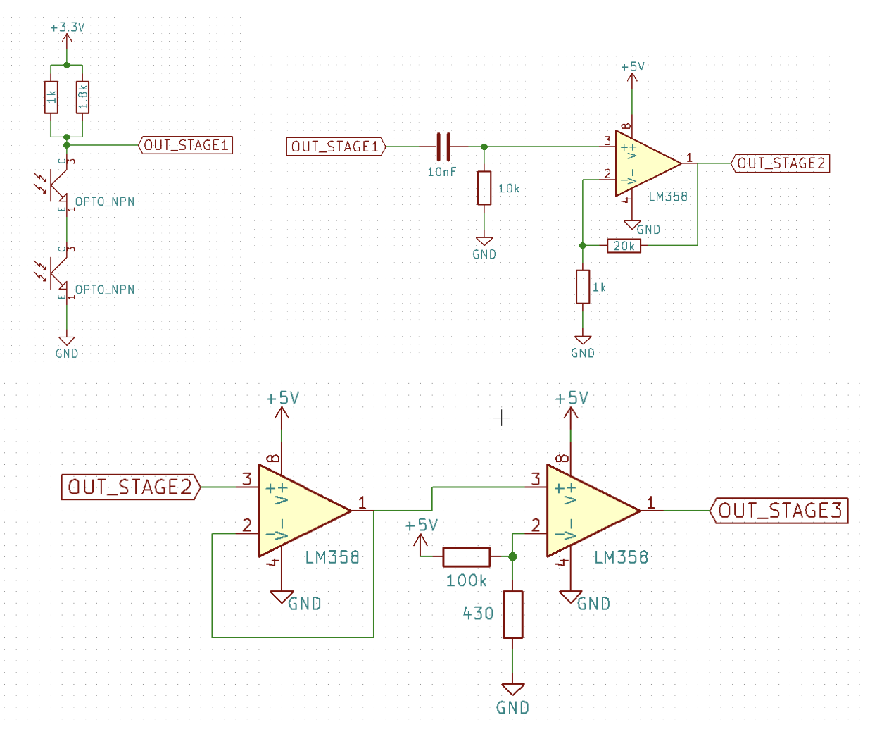
Broadcasting Information and the GUI
All of our radio communication and GUI setup was done in Lab 3 and hasn’t changed since then, as it worked perfectly back then and for the rest of the semester. We used a pair of Nordic nRF24L01+ transceivers, each attached to our two Arduinos to allow communication. The base station Arduino was connected to a laptop to display the GUI, which is run from a Python script and is written by the TAs. The GUI requires Python 2.7, can be found here.
To use the radios in our code, we included the RF24 Arduino library. The radio is set up in the setup() method of the Arduino code, which is based on the “Getting Started” sketch. We changed the pipe identifier numbers according to Lab 3’s requirements. We also wrote a broadcast() method that covers broadcasting a location’s information to the other radio. In the method, we first build the packet/message to be broadcast, then we send the message and wait for a response from the other radio. If we timeout, which means no response was received, the method returns false so we can try again, otherwise it returns true because it was a success. We found that the radio communication worked fine even when standing 15 feet apart, which we deemed more than enough for the final competition. We also have never lost a packet, so we did not have to deal with what to do when a packet is lost. We only call broadcast() when we explore a new node, which saves time when traversing already discovered areas. Our other Arduino has its own code that sets up its radio in a similar fashion and continuously listens for new packets, breaking them down when received according to the protocol below and sending the extracted information to the GUI.
Our protocol used when broadcasting is a total of 16 bits (2 bytes) and breaks down like so:
(4 bits) x, (4 bits) y, [(1 bit) explored, (3 bits) treasures, (4 bits) walls: NSEW]
The 8 bits in square brackets represent the bits we store in our global maze 2-D array that the robot updates as it explores. The rows of the 2-D array represent x coordinates and the columns are y coordinates. Although fairly unoptimized, this simple encoding scheme allowed the GUI to act independently from the robot entirely, remaining unchanged as the robot's capabilities changed. We also included global constants that represented, when converted to binary, the one set bit of each piece of information that we want to check for later on in the code, making it much easier to write code. For example, if we want to check if an explored node has a north wall, we would take the 8 bits representing the information about that node, which is stored in the maze 2-D array, and bitwise AND it with our bit-mask for a north wall, which is 00001000, or decimal 8. If the result is 0, then there is no wall, otherwise there is! Having the GUI's presence simplified testing immensely.
DFS Algorithm
We decided to use the depth first search (DFS) algorithm because it is a simple and complete search technique, good enough for a 9x9 maze within the limited memory available on the Arduino. Using this algorithm, the robot would traverse the maze by moving forward as far as it could (until reaching a dead end- either by being surrounded by walls, explored nodes, or both). When it could not move any further, it would backtrack until reaching a node with unexplored edges, continuing the DFS.
Because this algorithm could potentially cause the robot to backtrack multiple times, wasting time that could be spent mapping unexplored nodes, we also implemented a greedy DFS algorithm that would use a greedy method to calculate the shortest path to get to the next unexplored node chosen by DFS, reducing the amount of time spent going back. The path would be calculated only using previously explored nodes, which guarantees a path to the next node. It is a more efficient algorithm than just DFS because DFS has to backtrack the exact path it came from. Our greedy heuristic was Manhattan distance. After implementing the greedy DFS and having a successful run on a practice 10x4 maze, we unfortunately found that this algorithm used more dynamic memory than was available on the Arduino for larger mazes, so ultimately we did not use it for the competition because simple DFS was able to complete 9x9 mazes without memory issues.
The following paragraph goes a little more in-depth as to how we implemented our DFS. First, we imported a data structure called a Stack Array, which we used to record the current path we’re on in the DFS. Then, we wrote a recursive DFS method, which takes in a coordinate (represented with x and y values) that we have not explored yet. In that method, we first check if we should move to the location with a helper method that returns true if this location is valid, is one step away, has not been explored yet, and is immediately reachable (no walls blocking the way). Then, if we are able to move to the location, we physically move the robot there, also with a helper method that takes a coordinate, under the assumption that it is immediately reachable. We push this new location onto the path stack, and explore it with a helper method that reads the wall sensors and updates the information we know about this location, marking it as explored. Then, we check if we’ve explored all the locations (which is rows times columns), and if we did then we stop the robot, otherwise we continue the DFS. We then call DFS on every valid coordinate in the four cardinal directions- the order of the calls depends on the current direction of the robot, so that we prioritize the north location, then east, then west, then south. This allows us to minimize the number of turns our robot makes. Lastly, if the robot hits a dead end, which happens when the robot is unable to call DFS on any of the adjacent locations, or all the possible DFS calls have returned, then it knows it must backtrack because there are more unexplored locations to discover, just not down this branch of DFS. It pops the current location from the path stack, peeks at the previous location, and then uses our helper move function to move back to that location, which is definitely one away and immediately reachable, since it came this way before. To start the DFS in the main loop() Arduino method, we first explore the starting location, which is (0, 0). Then we add (0, 0) to the path stack, and call DFS on (1, 0). After that call returns, the robot ends up at (1, 0), so we move the robot back to (0, 0) and call DFS on (0, 1) to explore the rest of the maze, since if nothing remained then the robot would have stopped sometime within the first DFS call. After the second DFS returns, which it shouldn’t unless some location is completely unreachable somehow, we stop the robot. This implementation allowed our robot to successfully avoid the wall right in front of it at the starting location in the competition’s final maze, because it first explored the node, seeing the wall in front of it, which caused the DFS on (1, 0) to immediately return, calling the DFS on (0, 1) next to explore the maze!
Camera and FPGA
An explanation of how our treasure detection algorithm narrowed down both colors and shapes can be seen in the Lab 4 and Milestone 4 pages on our website. An explanation of how to program the DE0-Nano to load our algorithm on boot can be found here. Although we had fairly reliable treasure detection, especially for red treasures, we ultimately did not integrate the camera and FPGA to the final design because this would have taken more time that we decided to use to improve our DFS algorithm and speed up our robot so we could map more of the maze in the alloted time. The additional components also would have increased our robot's weight, shifting its center of gravity backwards and increasing the chance of a capsize.
At the competition, the Angry Bot more than exceeded our expectations, but some improvements to the system could have been done if we had more time and less restricting physical constraints. To start out, the camera and FPGA could have been mounted and integrated to the robot to provide treasure detection functionality. A better algorithm for handling robot avoidance could have been implemented. For example, we were working on an algorithm where the Angry Bot would move backwards to the previous intersection and continue with DFS from there, but we did not have enough time to get this working properly and there was also the issue that if there was a robot behind it, the Angry Bot would not be able to detect it due to its limited field of detection with the provided components. We also had a working greedy DFS algorithm that worked faster than a regular DFS (as mentioned in the DFS section), but due to the limited memory on the Arduino, we were not able to use this at the competition.
If given more time, we would look further into alternative algorithm implementations which would decrease backtracking, as well as better utilize simulations in order to determine the correctness and efficiency of our algorithm. Lastly, we found that during the competition, our robot would sometimes “jump” a bit over some intersections, causing it to miss those intersections. We had never seen it do that before, so we are not entirely sure of the problem, but we think it may lie in both the slightly uneven maze and also our sudden stopping and starting of our motors at every intersection, even though it hasn’t caused a problem before. Given more time, we would try to fix this issue to allow for smooth driving and consistent maze exploration.
All other functionality however, was very reliable. Changing the size of the robot’s wheels to be significantly larger a day before the competition was, although risky, a huge boost to speed and line-sensing accuracy. After many hours of work, line following, wall detection, tone detection, base station communication and the DFS worked very well together, which was the edge the Angry Bot needed to take home the first place trophy.